Method of compensating for image faults in an x-ray image recording

a technology of image faults and image recording, applied in the field of compensating for image faults in x-ray image recording, can solve the problems of reducing intensity, affecting the image, and affecting the image itsel

Inactive Publication Date: 2007-01-02
SIEMENS HEALTHCARE GMBH
View PDF5 Cites 8 Cited by
  • Summary
  • Abstract
  • Description
  • Claims
  • Application Information

AI Technical Summary

Benefits of technology

[0012]The summed values of the individual columns which form a one-dimensional vector can be smoothed by multiple lowpass filtering. In this way individual extreme values can be filtered out.

Problems solved by technology

The problem here is that the reduction in intensity at the edge of the x-ray image may not amount to more than 40%, defined by the ICE (Convention 606271978).
This means that the allowable distance range between the tubes and the detector in which the system may be operated is limited.
Furthermore the shadows themselves then disturb the image when the system is operated in the valid range.
In addition the shadowing can make diagnosis of the illness images more difficult.
It has been shown however that this model can only reproduce the intensity reduction behavior of anti-scatter grids imprecisely.
The deviations arising when the formula is applied are attributed to the fact that unknown variables such as incorrect grid positioning, grid defects or the Heel effect cannot be taken into account by Boldingh's formula.

Method used


Image

  • Method of compensating for image faults in an x-ray image recording
  • Method of compensating for image faults in an x-ray image recording
  • Method of compensating for image faults in an x-ray image recording

Examples


Embodiment Construction

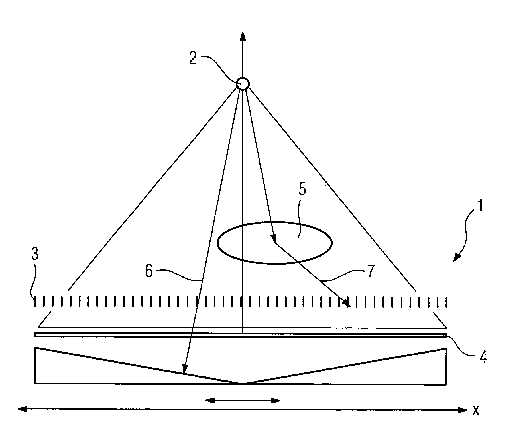
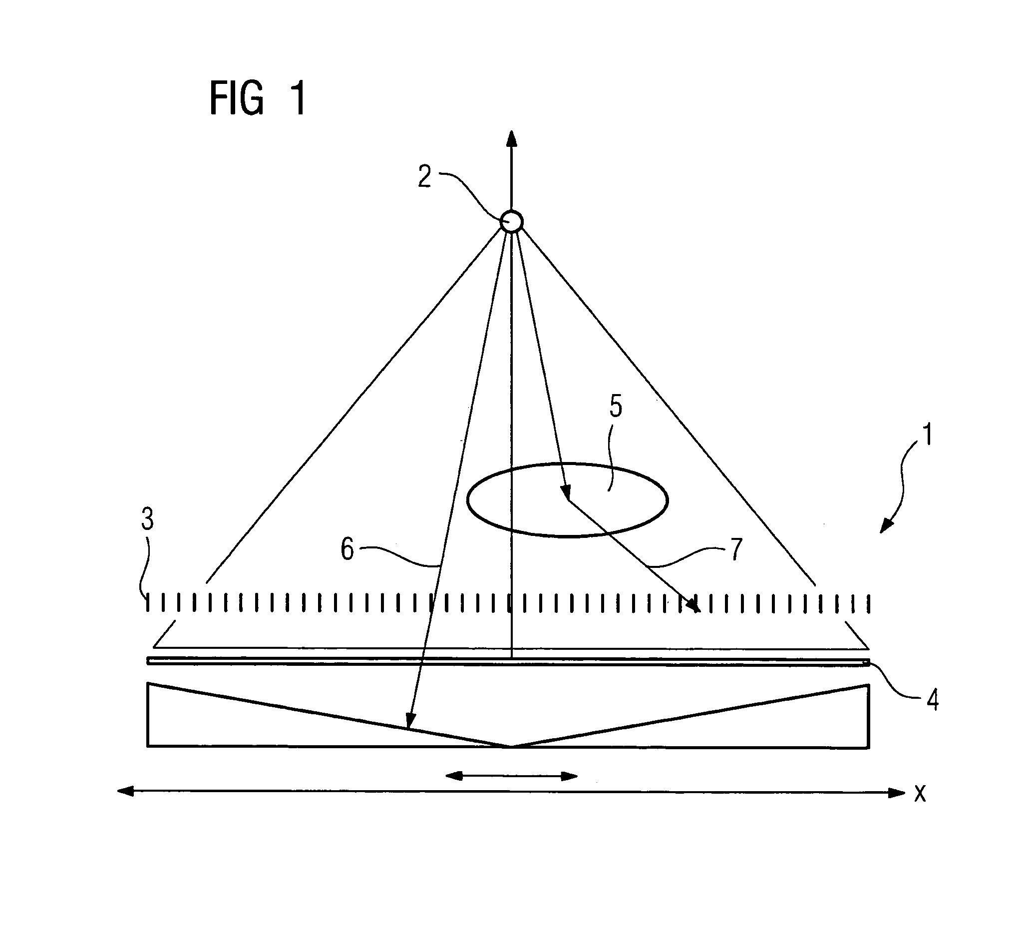
[0023]The x-ray system 1 shown in FIG. 1 consists of a schematic diagram of an x-ray tube 2, an anti-scatter grid 3 and an image detector 4 arranged below the anti-scatter grid. On illumination of an object 5, which is located between the x-ray tube 2 and the anti-scatter grid 3, direct information-bearing primary radiation 6 passes through the object 5 to reach the detector 4. A part of the radiation however is deflected by inhomogeneities, for example bones, in the object and thus becomes scattered radiation which disturbs the image. This is subsequently blocked off by the lead laminations of the anti-scatter grid 3. In this way scattered radiation 7 which disturbs the image is prevented from reaching the detector 4.

[0024]With the x-ray system 1 the x-ray tube 2 is adjustable vertically so that different distances between the x-ray tube 2 and the detector 4 can be set. Since the individual lead strips from which the anti-scatter grid is constructed are inclined at a slight angle, ...


PUM

PropertyMeasurementUnit
focal lengthaaaaaaaaaa
distancesaaaaaaaaaa
image brightnessaaaaaaaaaa

Abstract

Method for compensating for image faults in a digital image recording which has been created by an x-ray system consisting of a radiographic source, an anti-scatter grid and a digital x-ray detector such as an image amplifier or a solid-state image detector, said image faults resulting from decentering, defocusing or defects in the anti-scatter grid or by the Heel effect and causing an intensity reduction of the primary radiation falling on the x-ray detector, characterized in that the actual reduction in intensity is measured through the anti-scatter grid and correction parameters are determined based on the measured values recorded which are then used to correct the x-ray image recording.

Description

CROSS REFERENCE TO RELATED APPLICATIONS[0001]This application claims priority to the German application No. 10 2004 027 163.1, filed Jun. 3, 2004 which is incorporated by reference herein in its entirety.FIELD OF INVENTION[0002]The invention relates to a method of compensating for image faults in a digital x-ray image recording which has been created by a radiographic source, an anti-scatter grid and a digital x-ray detector such as an image amplifier or solid-state image detector, said image faults having been caused by decentering, defocusing or defects of the anti-scatter grid or by the Heel effect and causing a reduction in the intensity of the primary radiation falling on the x-ray detector.BACKGROUND OF INVENTION[0003]Anti-scatter grids are used in x-ray systems so that when an object under examination is illuminated with x-rays only direct information-bearing primary radiation reaches the detector from the x-ray tube. The scattered radiation which makes the image noisy is blo...

Claims


Application Information

Patent Timeline
Patent Type & Authority Patents(United States)
IPC IPC(8): G21K1/02G03B42/02A61B6/00A61B6/03A61B6/06G01N23/04G21K1/00H05G1/64
CPCG06T5/008G06T2207/30004G06T2207/10116A61B6/5258
Inventor PFISTER, MARCUS
Owner SIEMENS HEALTHCARE GMBH
Why Eureka
Try Eureka