Dynamic remediation of soil and groundwater

a soil and groundwater technology, applied in the field of environmental remediation, can solve the problems of contaminated soil reclamation, radioactive decontamination, nuclear engineering, etc., and achieve the effect of optimizing the remediation

Inactive Publication Date: 2007-01-02
RIDGE TECHN
View PDF5 Cites 5 Cited by
  • Summary
  • Abstract
  • Description
  • Claims
  • Application Information

AI Technical Summary

Benefits of technology

[0029]The current methodology of the industry uses “brute force” without the use of any feedback from the operation of the remediation system as to how it is performing in effecting the clean up or even whether the selected system uses the appropriate technology. Accordingly, it can be seen that there is yet a need in the art for a method and apparatus for providing soil and groundwater remediation which takes advantage of performance information in order to utilize the appropriate techniques and resources at the appropriate time and to optimize the remediation being performed. It is to the provision of such a remediation method and apparatus that the present invention is primarily directed.

Problems solved by technology

This is in stark contrast to the prior art arrangements which utilize few remediation wells in a wooden (fixed) manner to accomplish remediation through a series of assumptions based on limited operational data in a somewhat uninformed way.

Method used


Image

  • Dynamic remediation of soil and groundwater
  • Dynamic remediation of soil and groundwater
  • Dynamic remediation of soil and groundwater

Examples


Embodiment Construction

[0046]The present invention may be understood more readily by reference to the following detailed description of the invention taken in connection with the accompanying drawing figures, which form a part of this disclosure. It is to be understood that this invention is not limited to the specific devices, methods, conditions or parameters described and / or shown herein, and that the terminology used herein is for the purpose of describing particular embodiments by way of example only and is not intended to be limiting of the claimed invention.

[0047]Also, as used in the specification including the appended claims, the singular forms “a,”“an,” and “the” include the plural, and reference to a particular numerical value includes at least that particular value, unless the context clearly dictates otherwise.

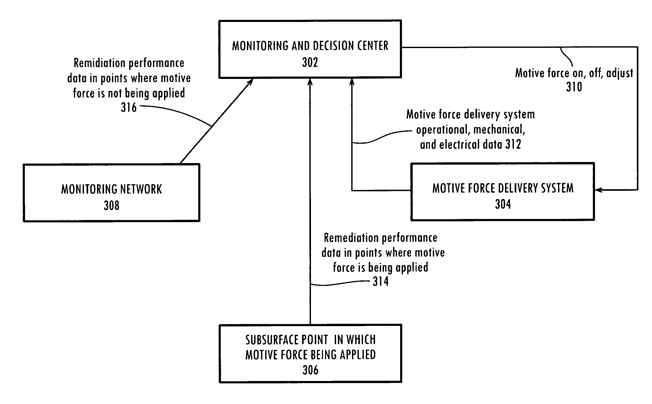
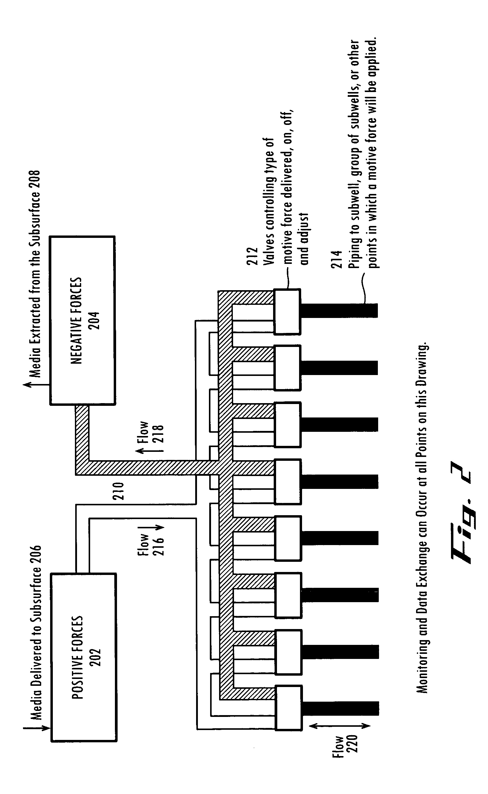
[0048]As used herein “motive force” indicates any action that can add or remove matter from the area to be remediated.

[0049]As used herein “influence” indicates any change in conditions...


PUM


Abstract

A method and system for improved environmental remediation. A method comprising establishing an initial remediation protocol; applying at least one initial motive force according to the initial remediation protocol; monitoring the effect on the site resulting from the application of the at least one initial motive force; modifying the remediation protocol to improve the performance of the remediation using information gleaned from the monitoring of the site; applying at least one motive force according to the modified remediation protocol; and repeating monitoring, modifying, and applying in a more or less continuous fashion until the remediation is complete.

Description

CROSS REFERENCE TO RELATED APPLICATION[0001]This application claims priority to U.S. Provisional Application No. 60 / 483,717, filed Jun. 30, 2003, hereby incorporated by reference in its entirety.FIELD OF THE INVENTION[0002]The present invention relates generally to the field of environmental remediation and, more specifically, relates to improving the process of environmental soil and groundwater remediation.BACKGROUND OF THE INVENTION[0003]A variety of methods involving the application of a motive force have been developed to remediate various types of soil and groundwater contamination of regulated materials. In the environmental remediation industry there is generally a lack of predictability in site remediation because subsurface soil and groundwater conditions are often heterogeneous and the delivery mechanisms for the motive forces are not efficient enough to overcome the heterogeneous conditions in a cost-effective manner. Current remediation processes are inefficient and som...

Claims


Application Information

Patent Timeline
Patent Type & Authority Patents(United States)
IPC IPC(8): B09C1/00
CPCB09C1/00B09C1/002B09C2101/00
Inventor ZOMER, PATRICK W.MACKING, ERIC J.
Owner RIDGE TECHN
Why Eureka
Try Eureka