
Transmitting apparatus and method and provision medium

a technology of transmission apparatus and transmission medium, which is applied in the direction of orthogonal multiplex, multiplex communication, multi-frequency code system, etc., can solve the problem of reducing the efficiency of frequency us

Inactive Publication Date: 2007-01-02
SONY CORP
View PDF16 Cites 13 Cited by
  • Summary
  • Abstract
  • Description
  • Claims
  • Application Information

AI Technical Summary

Benefits of technology

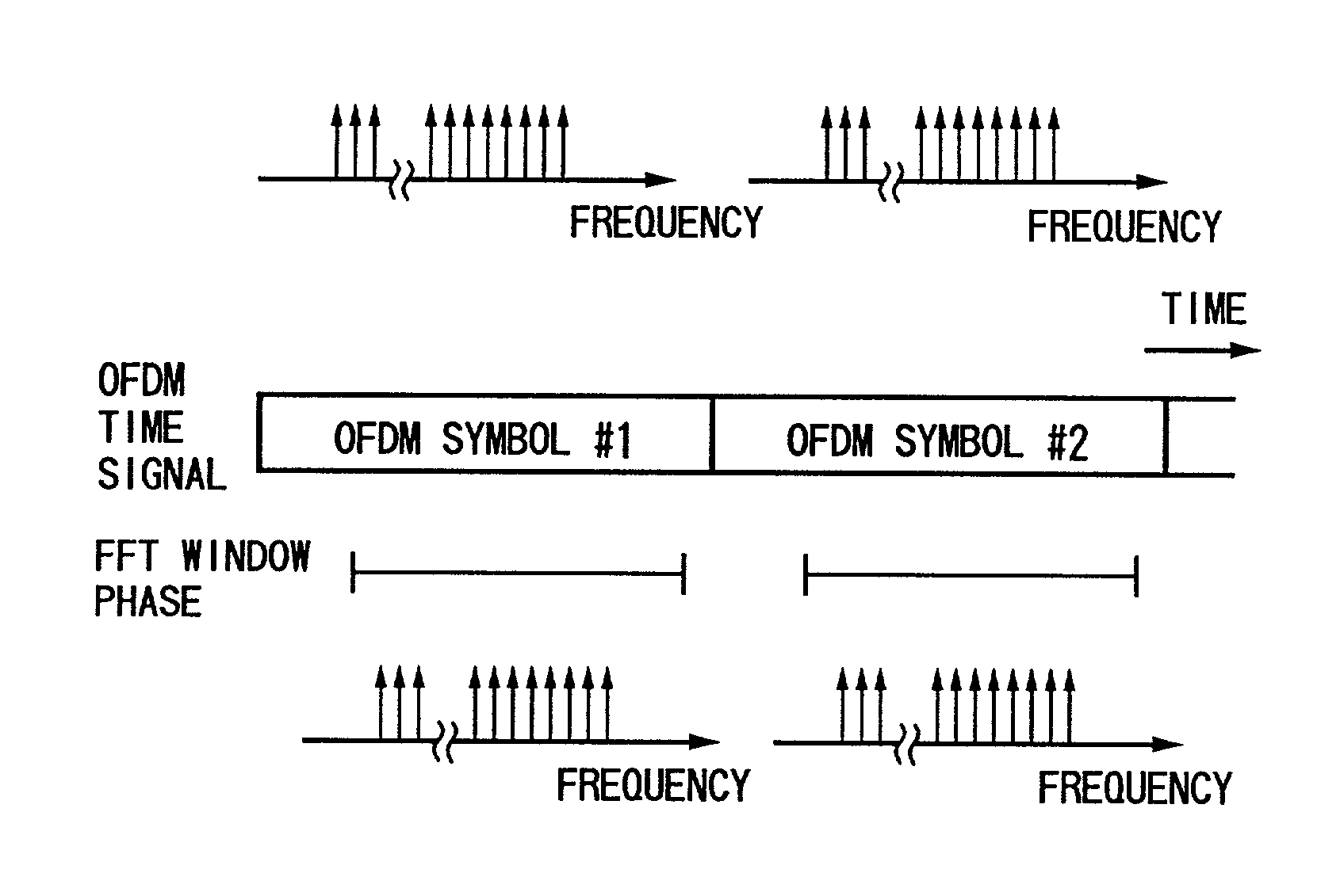
The present invention aims to enable a desired signal to be obtained without interference from adjacent signals, even without providing a guard band. The invention includes a transmitting apparatus and a method for generating a first clock and a second window signal to modulate an OFDM signal in accordance with information. The second clock is generated from the window signal and is used to control the transmission interval of OFDM signals. The technical effect of the invention is to enable a carrier interval between adjacent signals to become a whole multiple of the interval of carriers adjacent to each other, without interference from adjacent signals.

Problems solved by technology

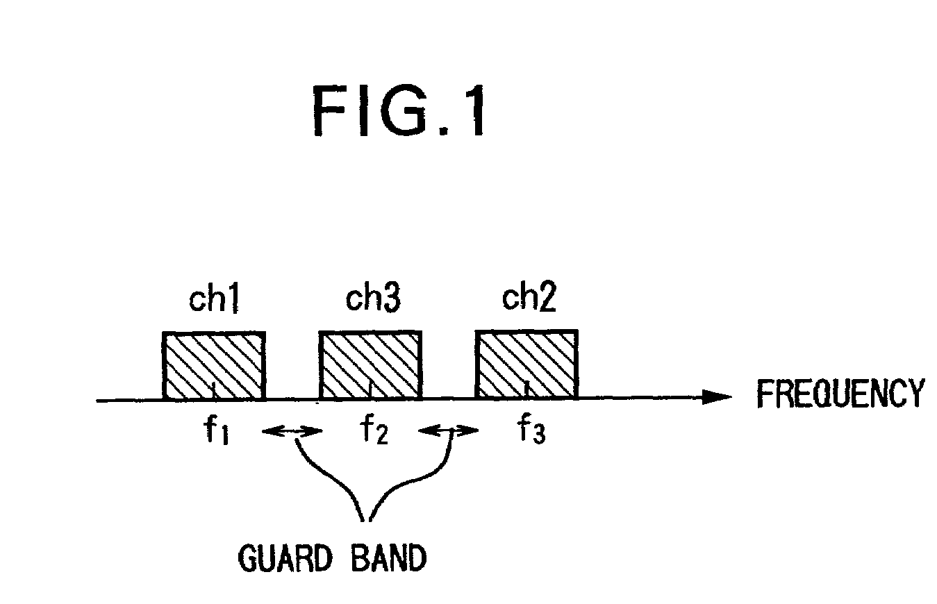
However, the provision of guard bands as mentioned above means a reduction of the efficiency of use of the frequency, so is not preferred from the viewpoint of effective utilization of the frequency.

Method used


Image

  • Transmitting apparatus and method and provision medium
  • Transmitting apparatus and method and provision medium
  • Transmitting apparatus and method and provision medium

Examples


Embodiment Construction

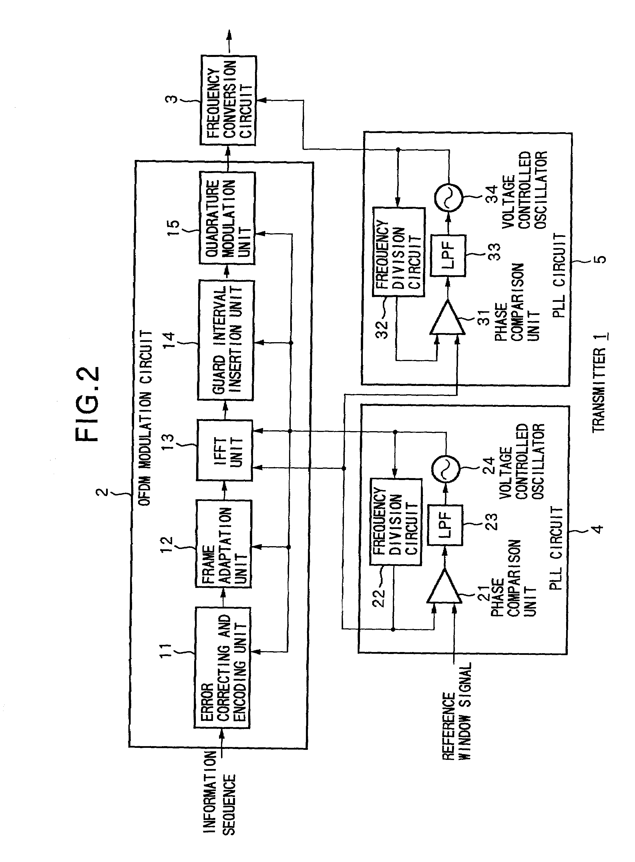
[0028]FIG. 2 is a block diagram of an embodiment of a transmitter to which the present invention is applied. A series of information input to an OFDM modulation circuit 2 of a transmitter 1 is corrected for error and encoded by an error correcting and encoding unit 11 and output to a frame adaptation unit 12. The frame adaptation unit 12 builds frames each comprised of synchronization use symbols, service identification use symbols, and information transmission use symbols. The signal formed into frames is input to an IFFT (inverse fast Fourier transform) unit 13 where it is subjected to an inverse Fourier transform (OFDM modulated) and then output to a guard interval insertion unit 14.

[0029]The guard interval insertion unit 14 inserts a guard interval to the input signal. In the OFDM modulation scheme, as shown in FIG. 3, a transmission signal is generated by combining carriers 1 through k as modulated waves modulated by using for example 64 QAM (quadrature amplitude modulation). T...


PUM


Abstract

Influence from an adjacent signal is prevented even if a guard band is not provided.A phase comparison unit 21 compares a reference window signal input to a PLL circuit 4 and a window signal supplied from a frequency division circuit 22 and outputs the comparison result to an LPF 23. The LPF 23 extracts a low frequency component from the input signal and outputs the same to a voltage controlled oscillator 24. The signal output from the voltage controlled oscillator 24 is supplied as a clock to units of an OFDM modulation circuit 2 and, at the same time, supplied to the frequency division circuit 22. The frequency division circuit 22 divides the frequency of the supplied signal to thereby generate a new window signal and supplies the same to an IFFT unit 13. Further, the generated window signal is supplied to a PLL circuit 5. The PLL circuit 5 generates a clock for controlling a frequency modulation circuit 3 based on the supplied window signal.

Description

TECHNICAL FIELD[0001]The present invention relates to a transmitting apparatus and method and a provision medium for the same, more particularly relates to a transmitting apparatus and method for transmitting a signal which can correctly detect a desired signal even without providing a guard band usually provided for preventing interference from an adjacent signal and a provision medium for the same.BACKGROUND ART[0002]The OFDM (orthogonal frequency division multiplexing) transmission system has tolerance against multipath interference, so is known as a transmission system suitable for digital transmission using terrestrial waves. The OFDM transmission system is being employed as a provisional system by the Japanese Telecommunications Technology Council for its digital terrestrial television broadcast system (hereinafter referred to as the “wideband ISDB-T” system) and digital terrestrial radio system (hereinafter referred to as the “narrowband ISDB-T system”).[0003]At the start of ...

Claims


Application Information

Patent Timeline
Patent Type & Authority Patents(United States)
IPC IPC(8): H04J11/00H04J3/06H04L27/26
CPCH04L27/2626H04L27/26265
Inventor IKEDA, YASUNARIIKEDA, TAMOTSUOKADA, TAKAHIRO
Owner SONY CORP
Learn More