Universal mold vacuum system

a vacuum system and universal mold technology, applied in the field of injection molding machines, can solve the problems of not providing control signals, unable to achieve more sophisticated vacuum control signals, and the modification of the standard injection molding machine to attach the limit switch not envisioned by the manufacturer can be difficult, and achieve the effect of quick movemen

Inactive Publication Date: 2007-01-02
MGS MFG GROUP
View PDF6 Cites 35 Cited by
  • Summary
  • Abstract
  • Description
  • Claims
  • Application Information

AI Technical Summary

Benefits of technology

[0007]The programmable logic controller may be flexibly programmed for complex logical combinations of existing signals to eliminate the need for special limit switches. Further, replaceable memory cartridges for the programmable logic controller allow ready transfer of the mold vacuum system among machines by switching the memory as a “personality module”.
[0029]The vacuum system may include an input receiving compressed air and a compressed air valve assembly communicating with the vacuum line. The programmable logic controller may further execute the stored program to create blowback timing signals from at least some of the control signals to the compressed air valve to provide compressed air to the mold.

Problems solved by technology

Standard machines normally employ proprietary control systems that do not provide control signals to activate the vacuum system at the proper time and duration.
This approach may not be suitable for creating more sophisticated vacuum control signals triggered by events or states not associated with a change in mold position, for example, as may occur in some two-shot molding applications.
Modification of the standard injection-molding machine to attach the limit switches not envisioned by the manufacturer can be difficult and the limit switches, once in place, are subject to damage and contamination.

Method used


Image

  • Universal mold vacuum system
  • Universal mold vacuum system
  • Universal mold vacuum system

Examples


Embodiment Construction

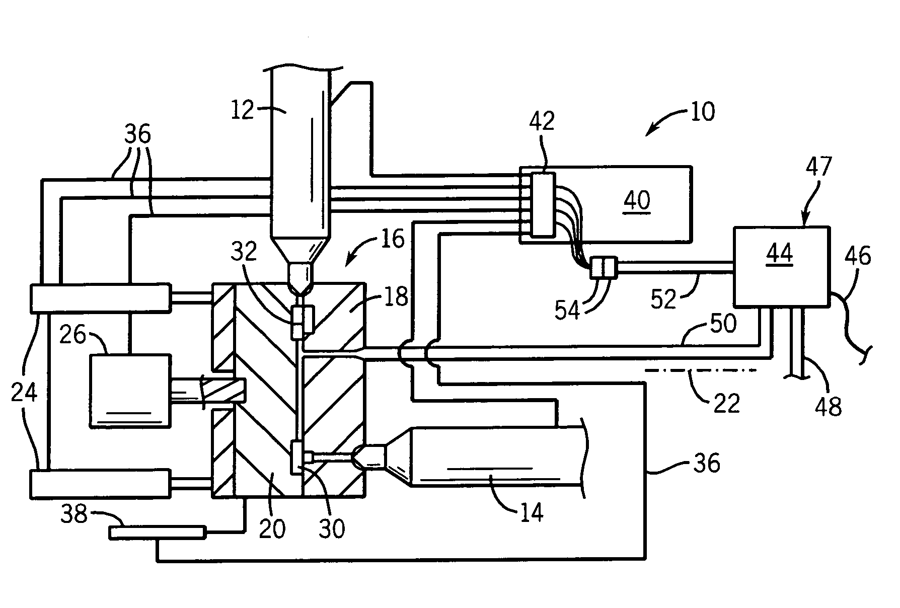
[0036]Referring now to FIG. 1, an injection-molding machine 10 for two shot molding includes a first injector 12 and second injector 14 for delivering two different thermoplastic materials to the mold 16.

[0037]The mold 16 includes a stationery mold portion 18 and a movable mold portion 20 that together define cavities 30 and 32. The movable mold portion 20 may be separated along a mold separation axis 22 to pull away from stationary mold portion 18 for the ejection of parts. This motion may be accomplished by hydraulic actuators 24 providing a mold clamping and opening according to methods known in the art.

[0038]For two shot molding, a hydraulic motor 26 may rotate the movable mold portion 20 about axis 22 to carry a molded part (not shown) produced in a cavity 30 after receiving material from injector 14 to a cavity 32. At cavity 32, the molded part may receive additional material from injector 12.

[0039]Generally, injectors 12 and 14 may communicate via runners all or partially wit...


PUM

PropertyMeasurementUnit
vacuum timingaaaaaaaaaa
vacuumaaaaaaaaaa
timeaaaaaaaaaa

Abstract

A controller for a mold vacuum unit uses a programmable logic controller to provide flexible translation of pre-existing signals present on the injection-molding machine avoiding the need for modification of that machine by the addition of limit switches or the like. Simple adjustment of real time of time delays is provided by the integration of two self-contained timer units working in conjunction with the fixed programming of the programmable logic controller. Removable memories for the programmable logic controller allow the vacuum unit to be used with a variety of different injection-molding machines.

Description

BACKGROUND OF THE INVENTION[0001]The present invention relates to injection molding machines and in particular to vacuum systems for such injection-molding machines.[0002]Injection-molding injects heated thermoplastic material at high pressures from an injector into a mold. The thermoplastic material cools within the mold and the mold may be opened and the part ejected.[0003]Gas trapped in the mold during the injection process may escape through the mold seams or through vents provided for that purpose. Alternatively, it is well known to apply a vacuum to the mold during the injection process to reduce gas entrapment. U.S. Pat. No. 4,573,900 entitled: Evacuation System for Injection-molding Machines, hereby incorporated by reference, describes a timer system controlling a pneumatic vacuum pump that may be used first, to apply a vacuum to the mold during certain periods of the injection cycle and second, to apply a positive pressure from the pneumatic line to the mold creating a “blo...

Claims


Application Information

Patent Timeline
Patent Type & Authority Patents(United States)
IPC IPC(8): B29C45/00
CPCB29C45/34B29C45/76B29C2945/76006B29C2945/76083B29C2945/76702B29C2945/76498B29C2945/76561B29C2945/76678B29C2945/76454
Inventor KOLANDER, STEVEN P.
Owner MGS MFG GROUP
Why Eureka
Try Eureka