Tempering device for printing presses

a technology of printing presses and temperature control, which is applied in the direction of office printing, letterpress printing, lighting and heating equipment, etc., can solve the problems of inability to separate cycles, inconvenient cooling fountain solutions, and high energy consumption of refrigerating plants

Inactive Publication Date: 2007-01-09
TECHNOTRANS
View PDF8 Cites 15 Cited by
  • Summary
  • Abstract
  • Description
  • Claims
  • Application Information

AI Technical Summary

Benefits of technology

[0017]Preferably, the process water initially passes through that chamber of the two chambers of the three-media heat exchanger, through which the cooling water of the free cooler cycle is flowing, so that the pre-cooling effect mentioned can be utilized, if the temperature conditions are suitable.
[0018]It is a particular advantage of the inventive solution that the process water exchanges heat in the heat exchanger not only with the compression refrigerating cycle but also with the free cooling cycle. In other words, that the free cooling cycle is not used directly as a process water cycle. In this way, different media can be circulated in the individual cycles. For example, the process water cycle can be formed by a fountain solution for the offset printing, whereas the free cooling cycle contains water, for example, also water with an anti-freeze agent. Each cycle may have a pipeline system of materials, which are particularly suitable for transporting the medium, such as a stainless steel in the case of corrosive media.

Problems solved by technology

Refrigeration plants, which have relatively high energy consumption, are required for these systems.
Since a separation of the cycles necessarily is impossible, this method is not suitable for cooling fountain solution.
However, since the temperature level of this cooling water is not always low enough, so that this cooling water can be used by means of a water / water heat exchanger for cooling the process water directly for cooling the friction rollers in the printing press, such systems are not being used at the present time.
The conventional systems have the disadvantage, in particular, that they use much energy and, correspondingly, have high operating costs.

Method used


Image

  • Tempering device for printing presses
  • Tempering device for printing presses

Examples


Embodiment Construction

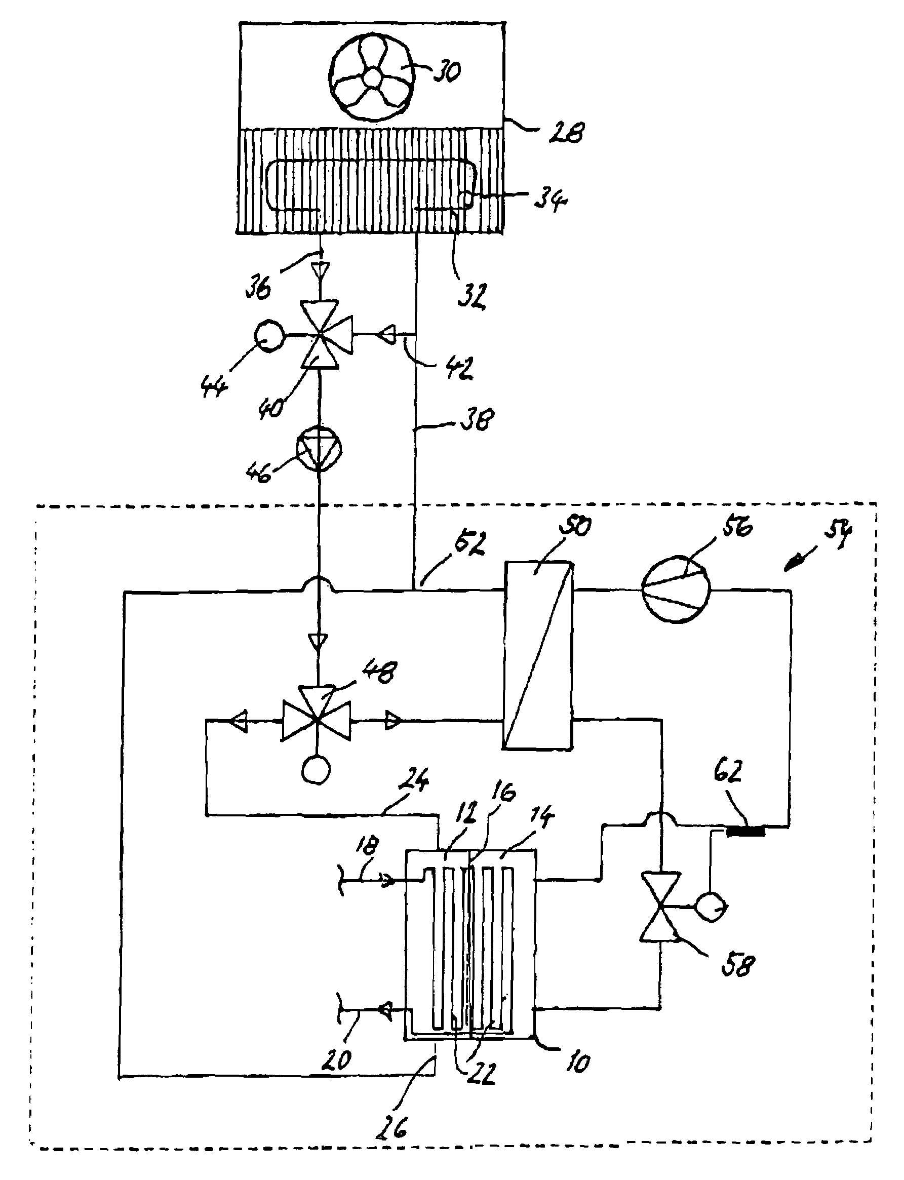
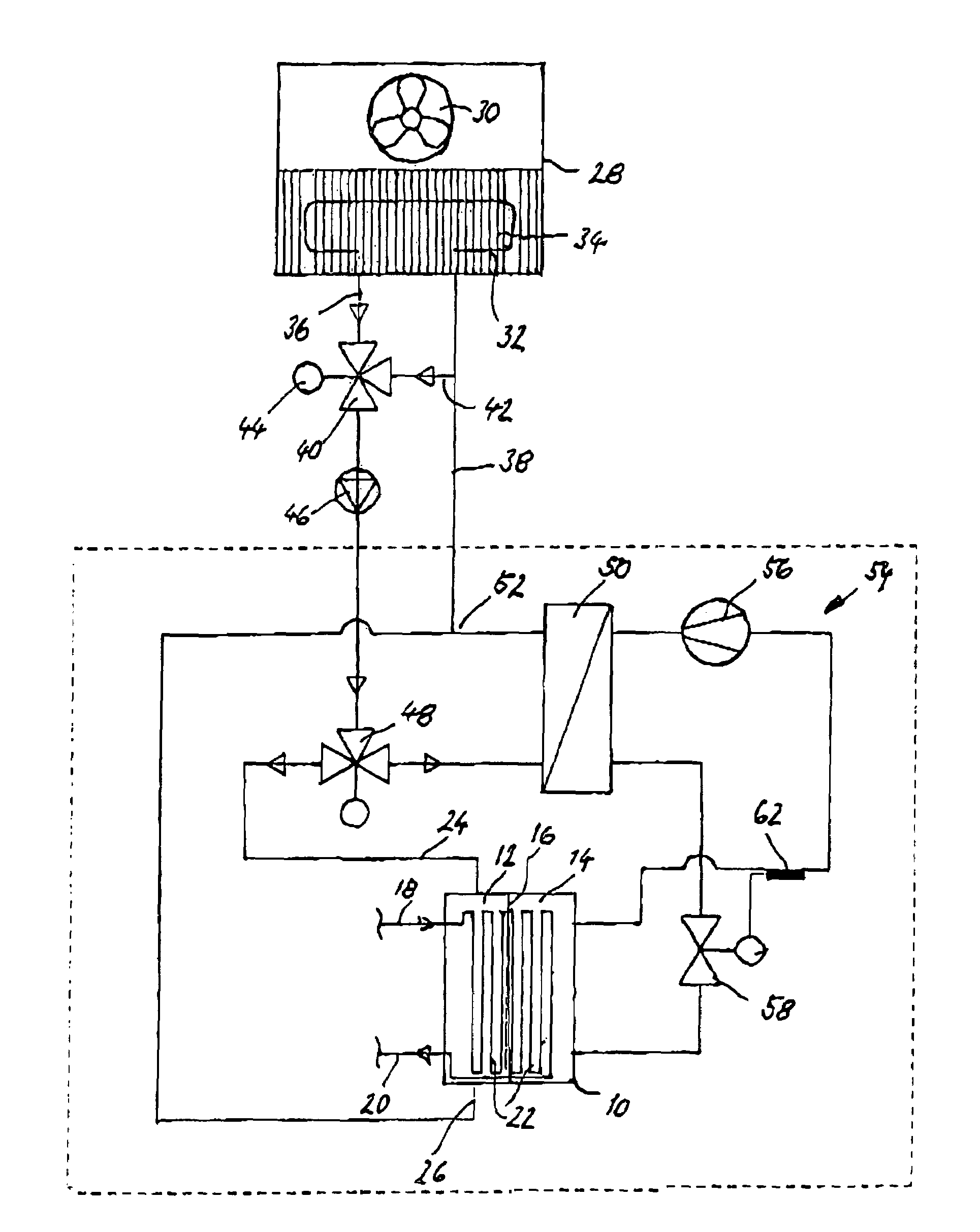
[0021]In the drawing, a three-media heat exchanger is labeled 10. This three-media heat exchanger 10 has a first chamber 12 and a second chamber 14, which, in the case of the embodiment shown, are combined into a spatial unit within a common housing and are separated only by a partition 16. The two chambers may, however, also form separate entities. An inlet pipeline 18 of a process water cycle enters the first chamber 12. On the other hand, an outlet pipeline 20 of this process water cycle leaves this chamber 12. The two pipelines 18, 20 are connected in the interior of the two chambers with coiled pipes 22, in which the process water flows through the two chambers 12, 14.

[0022]The inlet pipeline 18 and the outlet pipeline 20 are connected outside of the three-media heat exchanger with a printing press, which is not shown.

[0023]The inlet 24 and outlet 26 of a free cooling cycle, which has a water-air radiator with a fan 30 as cooling source, are connected with the first chamber 12 ...


PUM


Abstract

A tempering device for printing presses, includes a compression refrigerating plant with a condenser and an evaporator, in which a coolant circulates in a compression refrigerating path, and a free cooling path, in which a coolant circulates. A process water path circulates a coolant for either printing rollers or a fountain solution for offset printing. A heat exchanger arrangement cools the process water path with the help of the compression refrigerating plant and/or the free cooling path. The heat exchanger arrangement includes a three-media heat exchanger, in which heat is exchanged between the process water path and the compression refrigerating plant as well as the free cooling path.

Description

BACKGROUND OF THE INVENTION[0001]The invention relates to a tempering device for printing presses with compression refrigerating plant with a condenser and an evaporator, in which a coolant circulates, a free cooling circuit, in which a coolant, especially water, circulates, a process water cycle, in which a coolant for printing rollers or a fountain solution for offset printing circulates, and heat-exchanger means for cooling the cycling process water with the help of the compression refrigerating plant and / or of the free cooling cycle.[0002]Various embodiments of tempering systems for printing presses are known. As a rule, they are cooling systems, since a certain amount of heating, which can affect the printing quality, necessarily occurs during the operation of the printing press. The cooling can take place by water cooling of the friction rollers with the help of a pipeline system passing through these rollers or, in the case of offset printing, by means of a cooled fountain so...

Claims


Application Information

Patent Timeline
Patent Type & Authority Patents(United States)
IPC IPC(8): B41F1/34F25B27/00B41F13/22B41F33/00
CPCB41F33/0054B41F13/22
Inventor HAAS, THOMASCRUZ, NICHOLASBARBERI, STEVEBARBERI, LOU J.
Owner TECHNOTRANS
Why Eureka
Try Eureka