Control device

a control device and control technology, applied in the direction of diaphragm valves, gearing, engine diaphragms, etc., to achieve the effect of reducing the acting of compressed air pressure, improving heat resistance and pressure resistance, and reducing the heat resistan

Inactive Publication Date: 2007-01-09
FUJIKIN INC
View PDF5 Cites 22 Cited by
  • Summary
  • Abstract
  • Description
  • Claims
  • Application Information

AI Technical Summary

Benefits of technology

[0006]When the piston of the control device of the invention moves down, the outer end of the pivotal member of the booster means moves down, thereby moving the pivotal member about the horizontal rod and moving the inner end of the pivotal member upward to move the valve stem upward. With the horizontal rod positioned closer to the pivotal member inner end, the downward force of the piston is transmitted as amplified to the valve stem. The metal bellows used for sealing off the compressed air admitting space obviates the need to use components, such as O-rings, which are inferior in heat resistance, while the use of the booster means serves to diminish the compressed air pressure acting on the metal bellows. Thus, the control device is improved in both heat resistance and pressure resistance and made suitable as a valve for use at high temperatures.

Problems solved by technology

The metal bellows used for sealing off the compressed air admitting space obviates the need to use components, such as O-rings, which are inferior in heat resistance, while the use of the booster means serves to diminish the compressed air pressure acting on the metal bellows.

Method used


Image

  • Control device
  • Control device

Examples


Embodiment Construction

[0008]An embodiment of the invention will be descried below with reference to the drawing. In the following description, the terms “left” and “right” refer respectively to the left- and right-hand sides of the drawing.

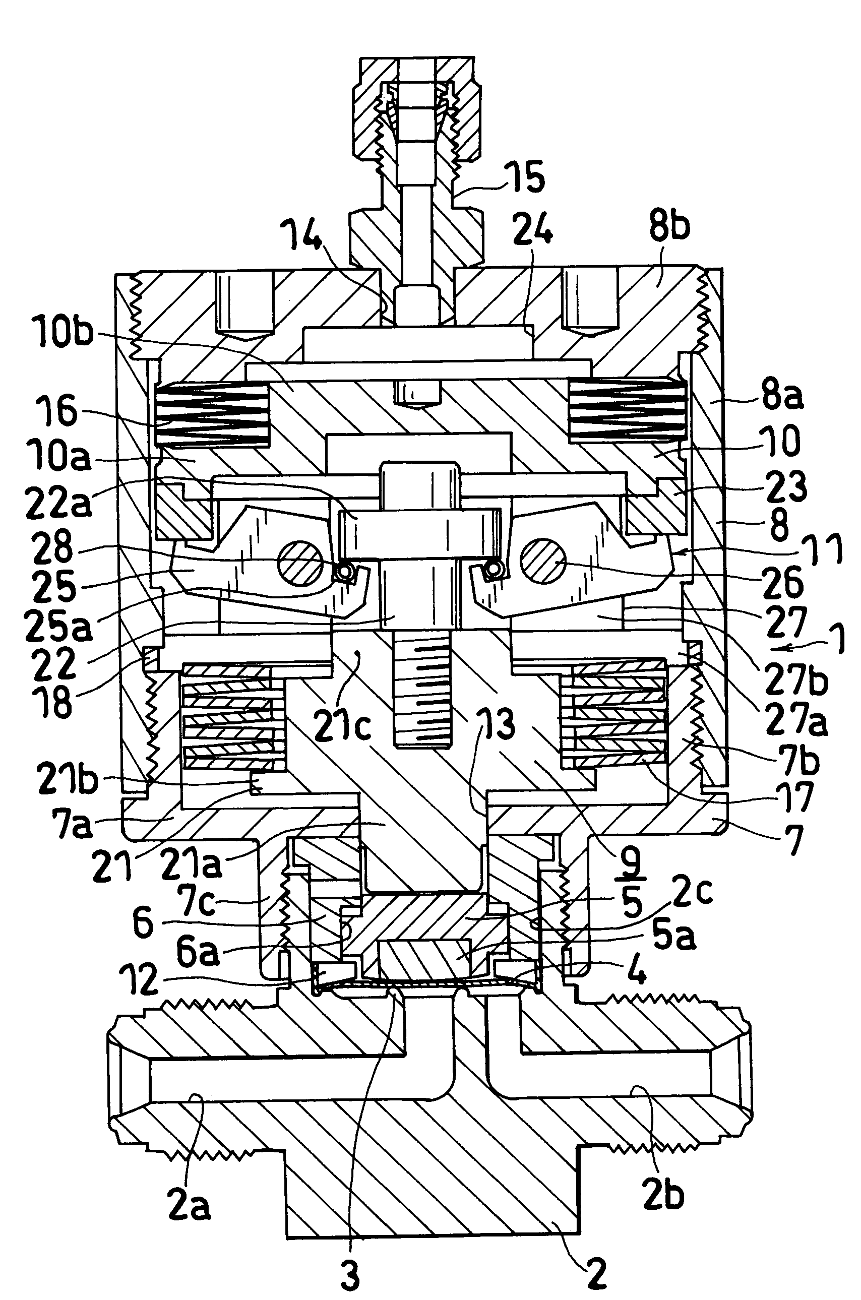
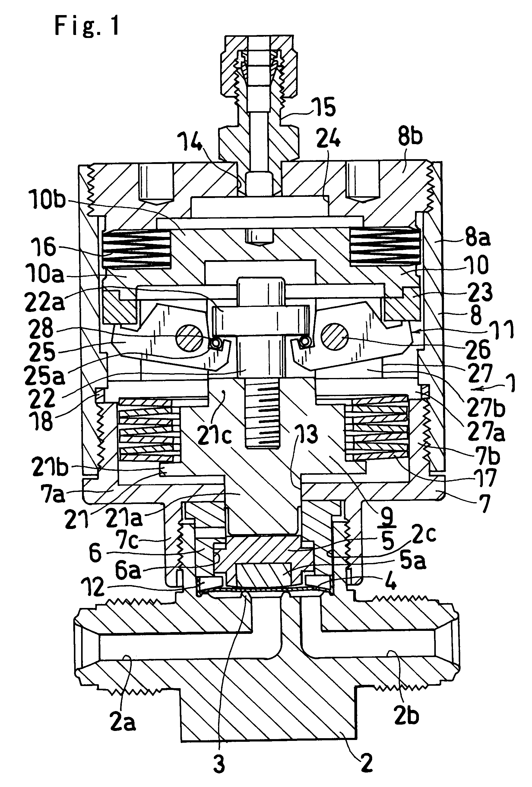
[0009]FIG. 1 shows an embodiment of control device of the present invention.

[0010]The control device 1 of this embodiment comprises a valve case 2 provided with a fluid inlet channel 2a and a fluid outlet channel 2b, an annular valve seat 3 formed around a peripheral edge defining an opening of the inlet channel 2a, a diaphragm (valve element) 4 movable into or out of pressing contact with the valve seat 3 for closing or opening the fluid channel 2a, a disk (valve element holder) 5 movable upward or downward and having a diaphragm holder 5a attached to its lower end, a bonnet 6 fitted around the disk 5, a lower casing 7 provided on an upper portion of the valve case 2, an upper casing 8 joined to the lower casing 7, a valve stem 9 disposed within a space defined by the...


PUM


Abstract

Booster means 11 for transmitting a force acting on a piston 10 to a valve stem 9 on amplification comprises pivotal members 25 each supported by casings 7, 8 so as to hold an outer end and an inner end thereof in contact with an outer peripheral portion of the piston 10 and a flange portion 22a formed on the valve stem 9 respectively from below and to be pivotally movable about a horizontal rod 26 positioned closer to the inner end. Metal bellows 16 are provided between an outer peripheral portion of the casing top wall 8a and the outer peripheral portion of the piston 10 for sealing off a compressed air admitting space.

Description

TECHNICAL FIELD[0001]The present invention relates to control devices, and more particularly to control devices which have booster means for transmitting the force acting on a piston to a valve stem on amplification and which are suitable as valves for use at high temperatures.BACKGROUND ART[0002]Already known are control devices which comprise a valve case having a fluid channel, a casing provided on an upper portion of the valve case, a valve stem disposed inside the casing and reciprocatingly movable upward and downward to thereby cause a valve element to open or close the fluid channel, a piston upwardly or downwardly movably provided inside the casing and defining a compressed air admitting space along with a top wall of the casing, and booster means for transmitting the force acting on the piston to the valve stem upon amplification (see, for example, the publication of JP-A No. 07-139648).[0003]Control devices having such booster means are termed high-temperature valves and u...

Claims


Application Information

Patent Timeline
Patent Type & Authority Patents(United States)
IPC IPC(8): F16K31/126F16H21/44F16K7/17F16J15/52
CPCF16K31/165F16K7/17F16K7/16F16K31/126F16H21/44F16J15/52
Inventor TANIKAWA, TSUYOSHIYAKUSHIJIN, TADAYUKINAKATA, TOMOHIRO
Owner FUJIKIN INC
Why Eureka
Try Eureka