Transverse connector system

a technology of transverse connectors and connectors, applied in the field of transverse connector systems, can solve the problems of increased soft tissue retraction and/or dissection, design of tightening mechanism, and disadvantages, and achieve the effect of simplifying the installation procedur

Active Publication Date: 2007-01-09
SEASPINE
View PDF15 Cites 36 Cited by
  • Summary
  • Abstract
  • Description
  • Claims
  • Application Information

AI Technical Summary

Benefits of technology

[0013]A transverse connector system for interconnecting two spinal rods in accordance with the present invention includes a connector, formed of one or more elongated members, adapted to span the distance between the rods. The connector has a rod receiving recess or groove on each end and a pin receiving bore adjacent each recess. A pin member, such as a set screw, is positioned within each pin receiving bore with the pins being arranged to be retracted within their associated bores to clamp the rods within the recesses and rigidly join the rods to the connector assembly. Preferably the pins are set screws with enlarged heads having beveled sides extending below the pin receiving bores so that the beveled sides, which may be straight or concave, engage the side of the rods to clamp the rods within the respective recesses. To simplify the installation procedure the set screws and pin receiving bores are preferably reverse threaded to accommodate clockwise rotation for the tightening procedure.
[0014]To facilitate the installation of the system while accommodating a reasonable spatial orientation of the spinal rods, the connector may be formed of first and second elongated members, a middle coupler and a locking screw. Each elongated member defines a longitudinal axis, a rod receiving groove on a proximal end thereof and a pin receiving bore adjacent the groove. A clamping pin is disposed in each pin receiving bore for securing the proximal end of the members to a respective rod. The distal end of the first member is provided with a threaded locking screw receiving bore. A ring coupler is mounted over the distal end of the first member for limited pivotal movement about an axis perpendicular to the longitudinal axis of that member. The coupler has an upper section with a cylindrical opening therein positioned over the locking screw receiving opening and a lower section of the coupler defines an internal curved surface through which the distal end of the second member extends to allow the second member to move along and rotate about its longitudinal axis relative to the first member. A locking screw threaded into the locking screw receiving bore in the coupler is arranged, when tightened, to lock the distal ends of the first and second members and the coupler together to maintain the spinal rods in the desired spatial orientation.

Problems solved by technology

This concept is disadvantageous in the clinical setting because bone or soft tissue protruding up to the lower surface of the spinal rod may restrict the ability of the surgeon in placing the lower hook portion underneath the spinal rod.
However, a clinical disadvantage of the '600 device is that the tightening mechanism is designed to extended parallel to the set screw, at the same oblique angle.
A deep and narrow surgical wound site greatly limits the angle at which an instrument may protrude resulting in the probability that increased soft tissue retraction and / or dissection may be required.
In addition, the nut tightening tool may disturb the tissue surrounding the nut during the tightening procedure at best or at worst may be deflected by the nut into adjacent vertebrae in the event that the tool slips off of the nut.
This type of nut has the same disadvantages as the Crozet et al nut.
The member having the truncated opening not only necessarily has a considerable width, but would be relatively expensive to manufacture.

Method used


Image

  • Transverse connector system
  • Transverse connector system
  • Transverse connector system

Examples


Embodiment Construction

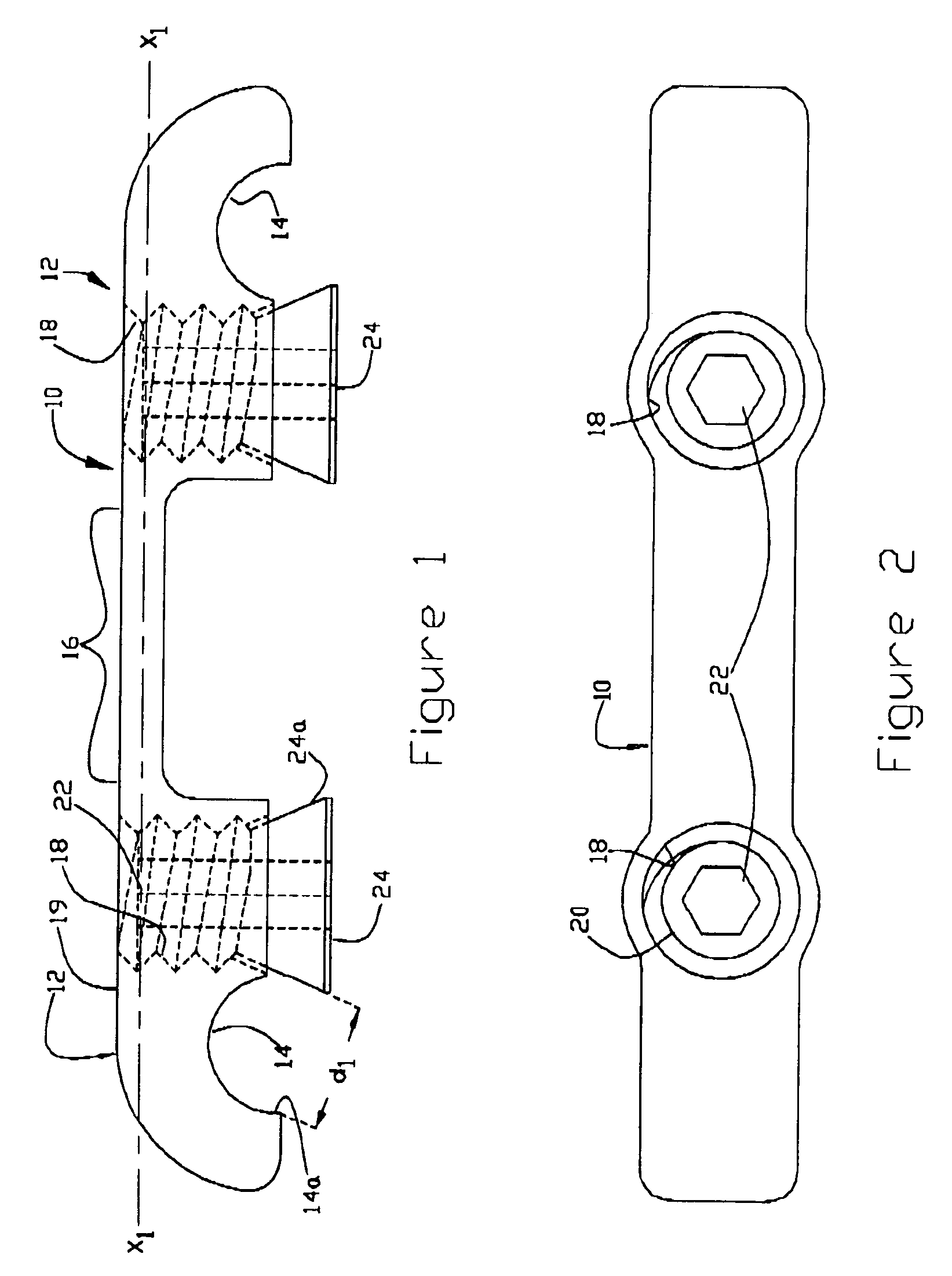
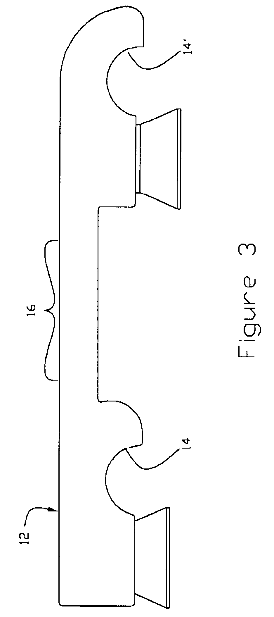
[0026]Referring now to FIGS. 1 and 2 an elongated unitary connector 10 is arranged to span the distance between two spinal rods. The connector is formed with end sections 12 defining rod receiving surfaces, grooves or recesses 14 and an intermediate bridge section 16. A threaded clamping pin, e.g., set screw, receiving bore 18 is located adjacent each groove 14 and extends at a right angle to the top surface 19 and the longitudinal axis X1 of the member 10 as illustrated. This arrangement overcomes the problems associated with prior art spinal rod securing systems which require the use of tightening instrumentation oriented at an angle to the wound site. A pin 20, in the form of a set screw with an internal hexagonal wrench receiving surface 22, e.g., to accommodate an allen wrench, and an enlarged head 24 is threaded into each bore 18 from the bottom to complete the system.

[0027]The rod receiving grooves 14 are generally semicylindrical in shape with a radius slightly greater than ...


PUM


Abstract

A transverse connector system for interconnecting two spinal rods includes a connector arranged to span the distance between the rods with a rod receiving recess and a pin receiving bore on each end. A pin member such as a set screw is deposited within each bore with an enlarged head protruding from the bottom of the connector so that when the set screw is retracted into the bore the head engages a side of the respective rod to clamp the rod within the recess. The connector may comprise two elongated members with a recess and pin receiving bore at one end of each member, a middle coupler which allows three degrees of freedom between the members to accommodate any anticipated spatial orientation between the members and a set screw for securing the other ends of the members together.

Description

RELATED APPLICATION[0001]This application is based on and claims priority of Provisional Application No. 60 / 483,947, filed Jul. 1, 2003, entitled Variable Transverse Connector for all common subject matter.FIELD OF THE INVENTION[0002]The present invention relates to a transverse connector system for interconnecting spinal rods that retain vertebrae in a fixed position. Another aspect of the invention is directed to a transverse connector system which is readily adjustable to join spinal rods of differing spatial orientations.DESCRIPTION OF THE PRIOR ART[0003]Numerous techniques have been employed to rigidly connect a pair of spinal rods for facilitating spinal fusion. A transverse connector system including one or more longitudinal members adapted to span the distance between two spinal rods along with a means for securing the end or ends of longitudinal member(s) to the spinal rods is generally used.[0004]For example, see U.S. Pat. No. 5,522,816 (“'816 patent”) issued to Dinello et...

Claims


Application Information

Patent Timeline
Patent Type & Authority Patents(United States)
IPC IPC(8): A61B17/70
CPCA61B17/7049
Inventor CORDARO, NICHOLAS M.
Owner SEASPINE
Why Eureka
Try Eureka