
Door locking control apparatus

a control apparatus and door locking technology, applied in the direction of electric controllers, ignition automatic control, instruments, etc., can solve the problems of increasing the difficulty of ensuring complete safety, false signals being generated, etc., and achieve the effect of improving reliability and safety

Inactive Publication Date: 2007-01-09
FORTRESS INTERLOCKS
View PDF4 Cites 1 Cited by
  • Summary
  • Abstract
  • Description
  • Claims
  • Application Information

AI Technical Summary

Benefits of technology

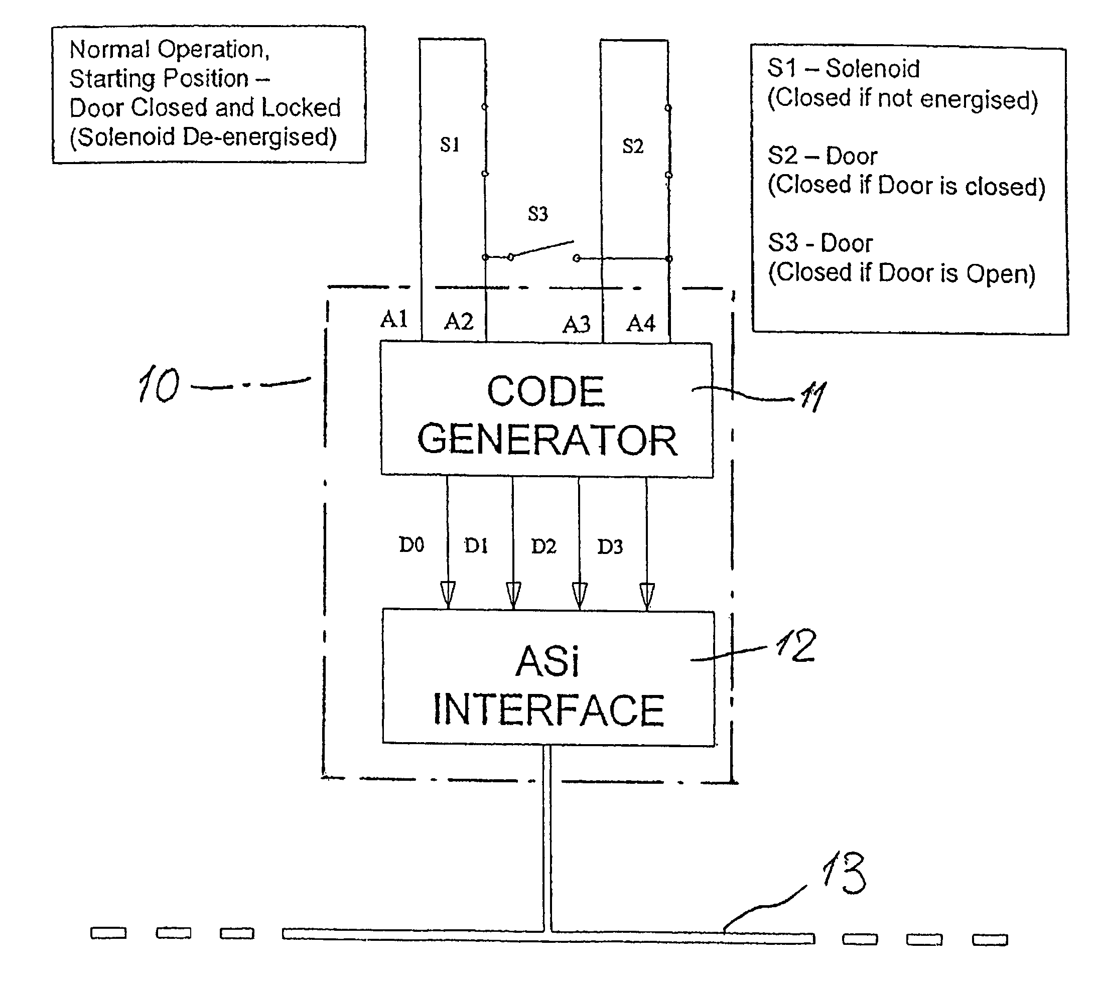
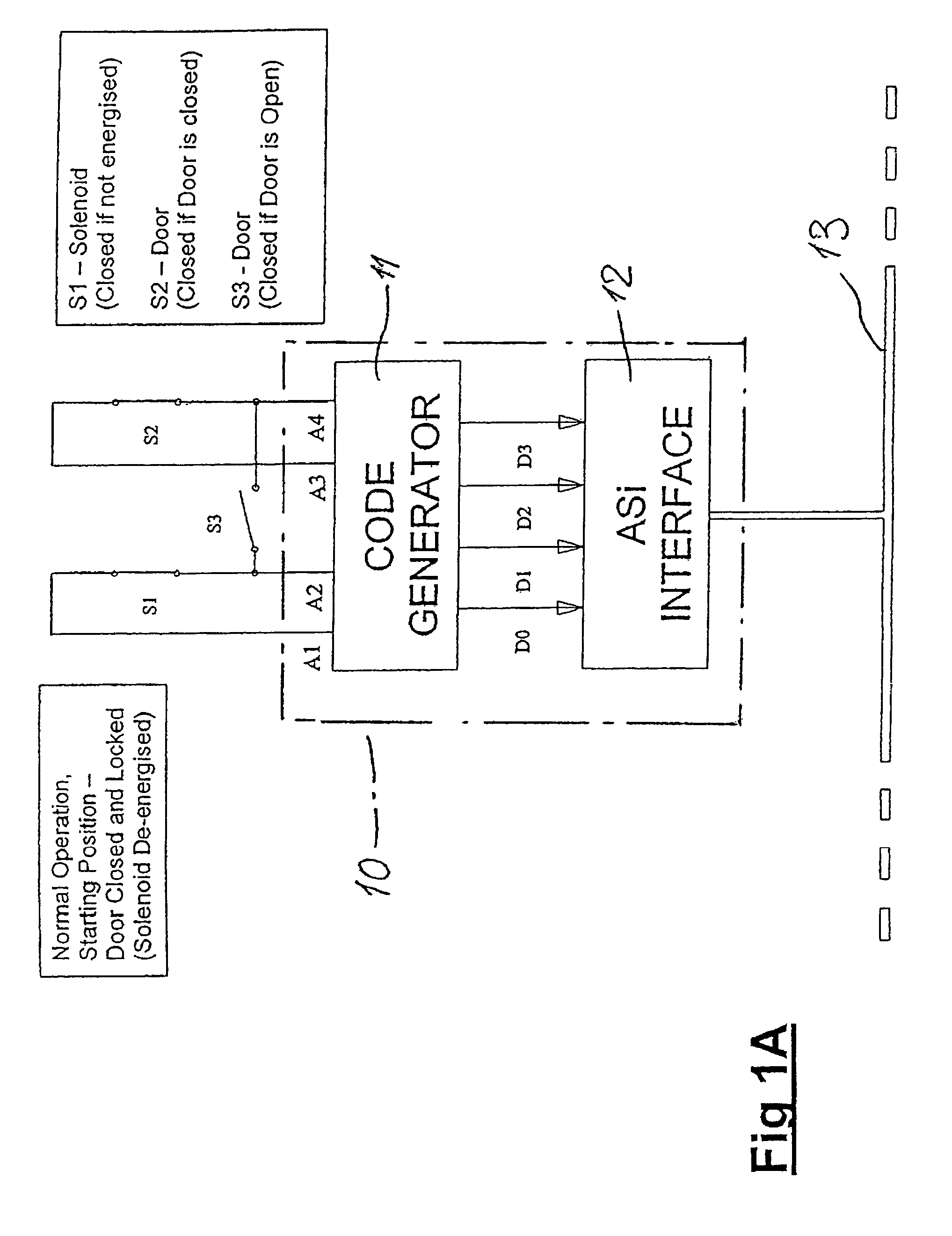
[0023]It will be appreciated that with the control apparatus of this invention, or when performing the method also of this invention, a relatively minor modification to a known system allows enhanced reliability and safety, in use. By furnishing a third sensor which is also associated with the door and which serves to link together either the two signal sources or the two sensing inputs of the processing unit, it is possible to detect unauthorised or inappropriate operation of either the first or second sensors. The processing unit, by outputting a suitable error-condition signal for example to a bus system controlling protected machinery or an industrial process, may inhibit operation until the origin of the error condition has been corrected. The error condition could arise either through malicious action by an unauthorised person, through failure of one or more components of the overall system, or on account of electrical interference.

Problems solved by technology

Further, with yet more complex industrial processes, it may be necessary to interlink guards associated with different machines or equipment, such that in the event access is gained at one location to a process, then other action is taken to ensure safety at all protected locations.
As the complexity has increased, it has become more and more difficult to ensure complete safety, having regard to the number of sensors which must be provided, together with all of the wiring associated with those sensors and the electrically-operated locks.
Further, and bearing in mind the electrically noisy environment within which such bus systems frequently have to operate, it is possible for false signals to be generated which permit restarting of machinery or which do not properly shut down machinery when that machinery is not properly guarded.

Method used


Image

  • Door locking control apparatus
  • Door locking control apparatus
  • Door locking control apparatus

Examples


Embodiment Construction

[0030]In order to allow the control apparatus of this invention to interface with a bus system including, for example, a computerised controller, the processing unit preferably has an interface unit which receives a code generated dependent upon the detected data streams present at its two sensing units and converts that code to a standardised format for supply to the bus. For example, the interface unit may convert the generated code to a known AS-i bus standard.

[0031]Each data stream advantageously comprises a stream of binary data, the first and second streams being dissimilar such that on linking by the third sensor, the linked data stream can be distinguished from the first and second streams. Preferably, therefore, each of the first and second data streams comprise a repeating string of binary data, of the same bit length and bit rate. In a typical system, each of the two data streams may comprise different four-bit binary codes.

[0032]Though satisfactory operation may be obtai...


PUM


Abstract

A control method and apparatus for a door-locking mechanism which includes an electrically-released latch, to lock the door closed. A processing unit sources first and second data streams each of a repeating string of binary data, the two strings being of the same bit length and bit rate, the processing unit also having two sensing inputs. A normally-open first switch is associated with the latch and connects the first data stream to the first sensing input other than when the latch is released, and a normally-open second switch is associated with the door and serves to connect the second data stream to the second sensing input so long as the door remains closed. A normally-closed third switch is also associated with the door and serves to link together the first and second sensing inputs when the door is not closed. The processing unit outputs a signal indicative of an error condition should the data stream which appears at either sensing input not be the expected stream.

Description

CROSS-REFERENCE TO RELATED APPLICATION[0001]This application claims priority to Great Britain Application No. 0223765.9, filed Oct. 14, 2002.BACKGROUND TO THE INVENTION[0002]a) Field of the Invention[0003]This invention relates to control apparatus for a door-locking mechanism including an electrically-released latch for locking an associated door closed. In particular, this invention concerns industrial doors, guards, screens and so on, to protect industrial machinery or other processes which could be hazardous to operators.[0004]b) Description of the Related Art[0005]With increasing emphasis on the health and safety of employees, it is becoming ever more important to provide competent and reliable protection for industrial machinery or equipment operating processes which are hazardous to the personnel in the vicinity of that machinery. Most such machinery now is fitted with various kinds of doors, guards, screens or other equipment which restricts access to the machinery or the pr...

Claims


Application Information

Patent Timeline
Patent Type & Authority Patents(United States)
IPC IPC(8): B60L1/00E05B17/22E05B47/00E05B47/02E05B63/00F16P3/08
CPCE05B17/22E05B47/0002E05B47/023E05B63/0052E05B2047/0067F16P3/08
Inventor STUBBS, TIMOTHY CHRISTOPHERGOLDING, MICHAEL JOHN CHAWNER
Owner FORTRESS INTERLOCKS
Learn More