Multicolored LED lighting method and apparatus

a multi-colored led and light source technology, applied in lighting applications, lighting and heating apparatus, instruments, etc., can solve the problems of inefficient transistor biasing, inability to change the bias of all three led transistors independently and simultaneously, and the apparatus has several disadvantages and limitations, so as to achieve simple visual inspection and facilitate reading.

Inactive Publication Date: 2007-01-09
PHILIPS LIGHTING NORTH AMERICA CORPORATION
View PDF546 Cites 453 Cited by
  • Summary
  • Abstract
  • Description
  • Claims
  • Application Information

AI Technical Summary

Benefits of technology

[0042]From the foregoing, it will be appreciated that PWM current control of LEDs to produce multiple colors may be incorporated into countless environments, with or without networks. For instance, FIG. 8 shows a hand-held flashlight can be made to shine any conceivable color using an LED assembly of the present invention. The flashlight contains an external adjustment means 5, that may be for instance a set of three potentiometers coupled to an appropriately programmed microcontroller 92 through respective A/D conversion means 15. Each potentiometer would control the current duty cycle, and thus the illumination intensity, of an individual color LED on LED board 25. With three settings each capable of generating a different byte from 0 to 255, a computer-controlled flashlight may generate twenty-four bit color. Of course, three individual potentiometers can be incorporated into a single device, such as a track ball or joystick, so as to be operable as a single adjuster. Further, it is not necessary that the adjustment means must be a potentiometer. For instance, a capacitive or resistive thumb plate may also be used to program the two or three registers necessary to set the color. A lens assembly 93 may be provided for reflecting the emitted light. A non-hand held embodiment of the present invention may be used as an underwater swimming pool light. Since the present invention can operate at relatively low voltages and low current, it is uniquely suited for safe underwater operation.
[0043]Similarly, the present invention may be used as a general indicator of any given environmental condition. FIG. 9 shows the general functional block diagram for such an apparatus. Shown within FIG. 9 is also an exemplary chart showing the duty cycles of the three color LEDs during an exemplary period. As one example of an environmental indicator 96, the power module can be coupled to an inclinometer. The inclinometer meas

Problems solved by technology

However, the apparatus has several disadvantages and limitations.
This means it is impossible in Phares to change all three LED transistor biases independently and simultaneously.
Also, biasing of the transistors is inefficient because power delivered to the LEDs is smaller than that dissipated in the biasing network.
This makes the device poorly suited for efficient illumination applications.
The transistor biasing used by Phares also makes it difficult, if not impossible, to interchange groups of LEDs having different power ratings, and hence different intensity levels.
However, no provision is made for precise and rapid control over the

Method used


Image

  • Multicolored LED lighting method and apparatus
  • Multicolored LED lighting method and apparatus
  • Multicolored LED lighting method and apparatus

Examples


Embodiment Construction

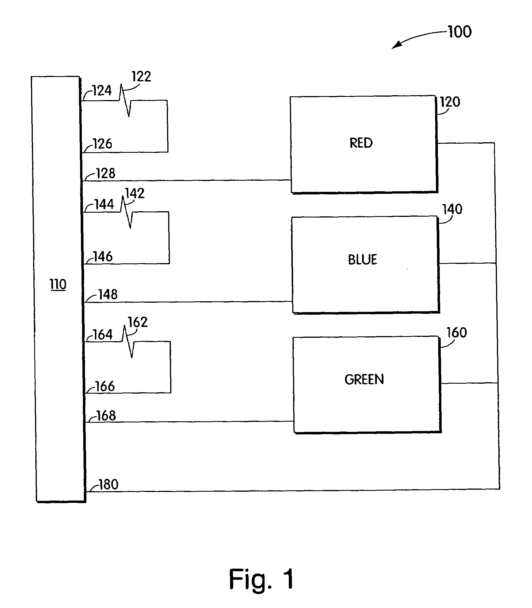
[0027]The structure and operation of a preferred embodiment will now be described. It should be understood that many other ways of practicing the inventions herein are available, and the embodiments described herein are exemplary and not limiting. Turning to FIG. 1, shown is an electrical schematic representation of a light module 100 of the present invention. FIGS. 4 and 5 show the LED-containing side and the electrical connector side of light module 100. Light module 100 is self-contained, and is configured to be a standard item interchangeable with any similarly constructed light module. Light module 100 contains a ten-pin electrical connector 110 of the general type. In this embodiment, the connector 110 contains male pins adapted to fit into a complementary ten-pin connector female assembly, to be described below. Pin 180 is the power supply. A source of DC electrical potential enters module 100 on pin 180. Pin 180 is electrically connected to the anode end of light emitting di...


PUM


Abstract

Apparatus and systems including one or more first LEDs, each first LED configured to generate first radiation having a first spectrum, and one or more second LEDs, each second LED configured to generate second radiation having a second spectrum different than the first spectrum. A diffuser is employed to blend the first radiation and the second radiation, when generated, so as to provide a uniform color of light having a visible spectrum based on a combination of the first spectrum and the second spectrum. One or more controllers are configured to control the first LED(s) and the second LED(s) such that visible light provided by the diffuser is perceived as one or more colors. In different aspects, the apparatus/systems may be configured to generate white light and/or multicolor light, may be formed to resemble conventional light bulbs, and may be arranged as a linear chain of nodes.

Description

CROSS REFERENCES TO RELATED APPLICATIONS[0001]This application is a continuation of application Ser. No. 09 / 971,367, filed on Oct. 4, 2001 now U.S. Pat. No. 6,788,011, which is a continuation of application Ser. No. 09 / 669,121, filed on Sep. 25, 2000 now U.S. Pat No. 6,806,659, which is a continuation of application Ser. No. 09 / 425,770, filed Oct. 22, 1999, now U.S. Pat. No. 6,150,774, which is a continuation of application Ser. No. 08 / 920,156, filed Aug. 26, 1997, now U.S. Pat. No. 6,016,038.BACKGROUND OF THE INVENTION[0002]The present invention relates to providing light of a selectable color using LEDs. More particularly, the present invention is a method and apparatus for providing multicolored illumination. More particularly still, the present invention is an apparatus for providing a computer controlled multicolored illumination network capable of high performance and rapid color selection and change.[0003]It is well known that combining the projected light of one color with t...

Claims


Application Information

Patent Timeline
IPC IPC(8): G05F1/00F21K99/00F21S8/00G09G3/14G09G3/20G09G3/32H05B37/02H05B44/00
CPCF21K99/00F21K9/137G09G3/14G09G3/2014G09G3/32H05B33/0803H05B33/0842H05B33/0857H05B37/02H05B37/0272H05B37/029F21K9/00F21Y2101/02G09G3/3283G09G2300/06G09G2310/0272G09G2320/0626G09G2320/0666Y02B20/383F21W2131/401F21K9/232F21Y2115/10H05B45/20H05B47/155Y02B20/30H05B45/325H05B45/395H05B47/165
Inventor MUELLER, GEORGE G.LYS, IHOR A.
Owner PHILIPS LIGHTING NORTH AMERICA CORPORATION
Why Eureka
Try Eureka