Display system

a display system and image technology, applied in the field of image display systems, can solve the problems of viewer's inability to give his or her own information, difficulty in providing space for installing multiple indicators, and the likelihood that the viewer could overlook important information, so as to selectively present one or more images

Inactive Publication Date: 2007-01-09
FURUNO ELECTRIC CO LTD
View PDF5 Cites 167 Cited by
  • Summary
  • Abstract
  • Description
  • Claims
  • Application Information

AI Technical Summary

Benefits of technology

[0007]This invention is intended to solve the aforementioned problems of prior art technology. Accordingly, it is an object of the invention to provide a display system which makes it possible to selectively pres

Problems solved by technology

The conventional onboard system has therefore been associated with the following problems:A number of expensive indicators are required.It is difficult to provide space for installing such multiple indicators.Since three different pictures

Method used


Image

  • Display system
  • Display system
  • Display system

Examples


first embodiment

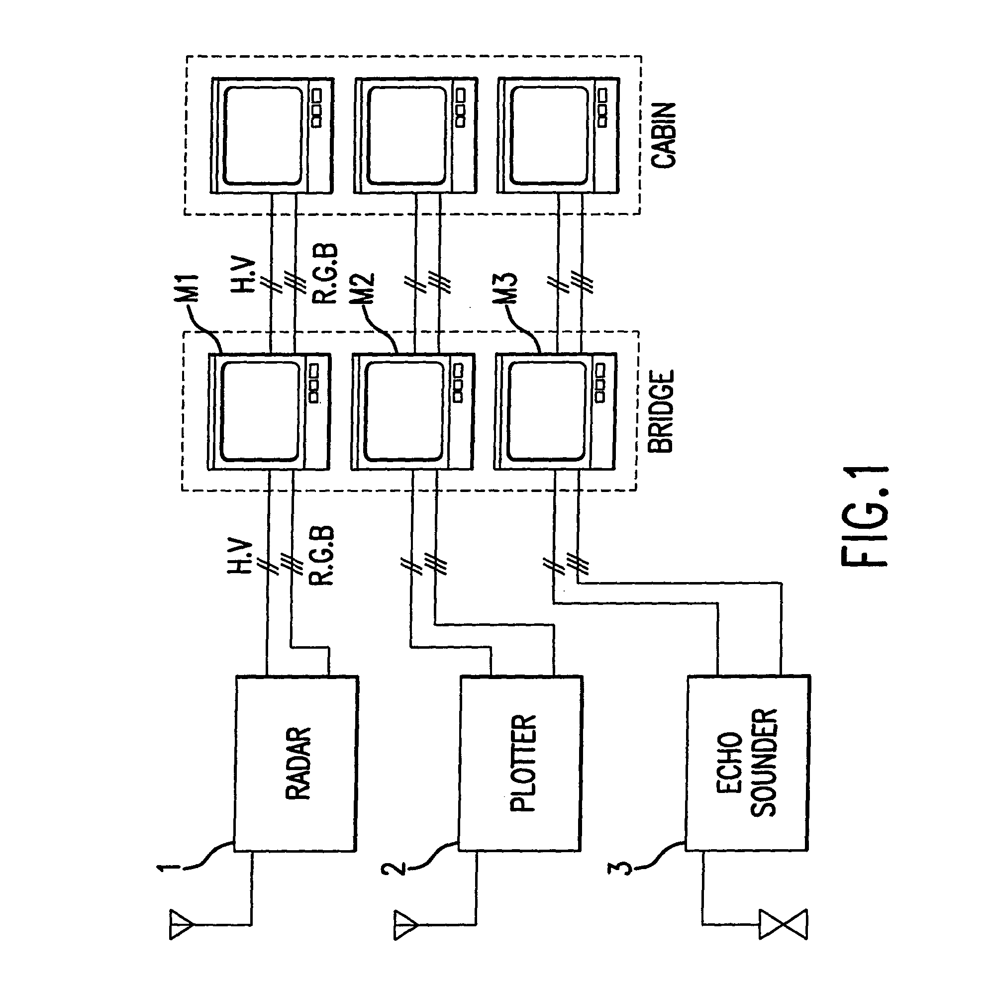
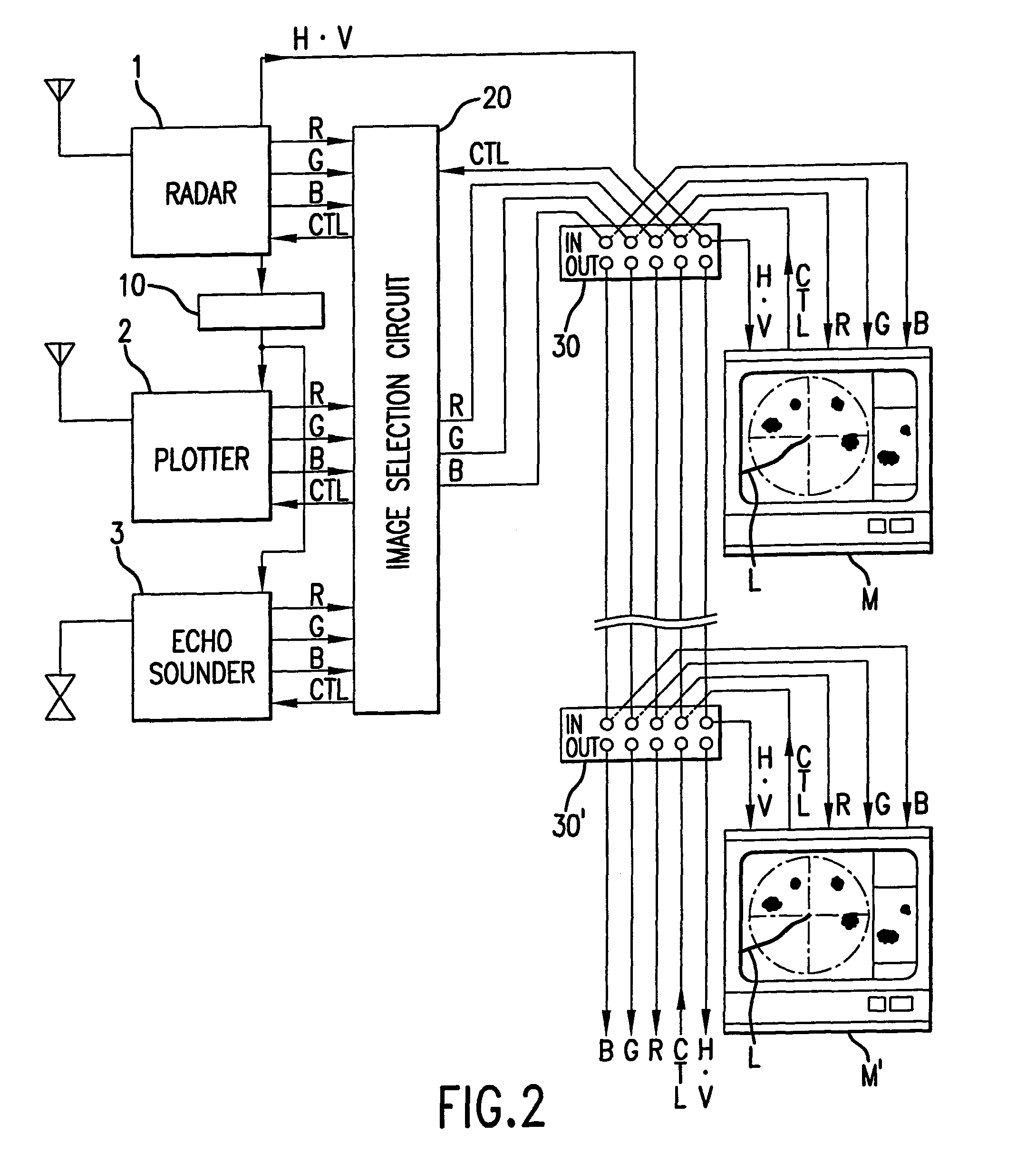
[0036]FIG. 2 is a general block diagram of a display system installed onboard a ship according to the invention, in which elements equivalent to those shown in FIG. 1 are designated by the same reference numerals or letters.

[0037]Designated by the numeral 10 in FIG. 2 is a synchronizing circuit which synchronizes the operational timing of a course plotter 2 and an echo sounder 3 with an internal synchronizing signal of a radar 1. The course plotter 2 incorporates, or is connected to, a GPS receiver. Designated by the numeral 20 is an image selection circuit which selects one or more desired image signals from those fed from the individual measuring devices 1–3 and combines the selected image signals. Indicated by 30 and 30′ are interconnecting terminal strips, each having a plurality of input terminals IN which are directly connected to their corresponding output terminals OUT. Indicated by M and M′ are indicators which individually receive R, G and B image signals as well as a hori...

second embodiment

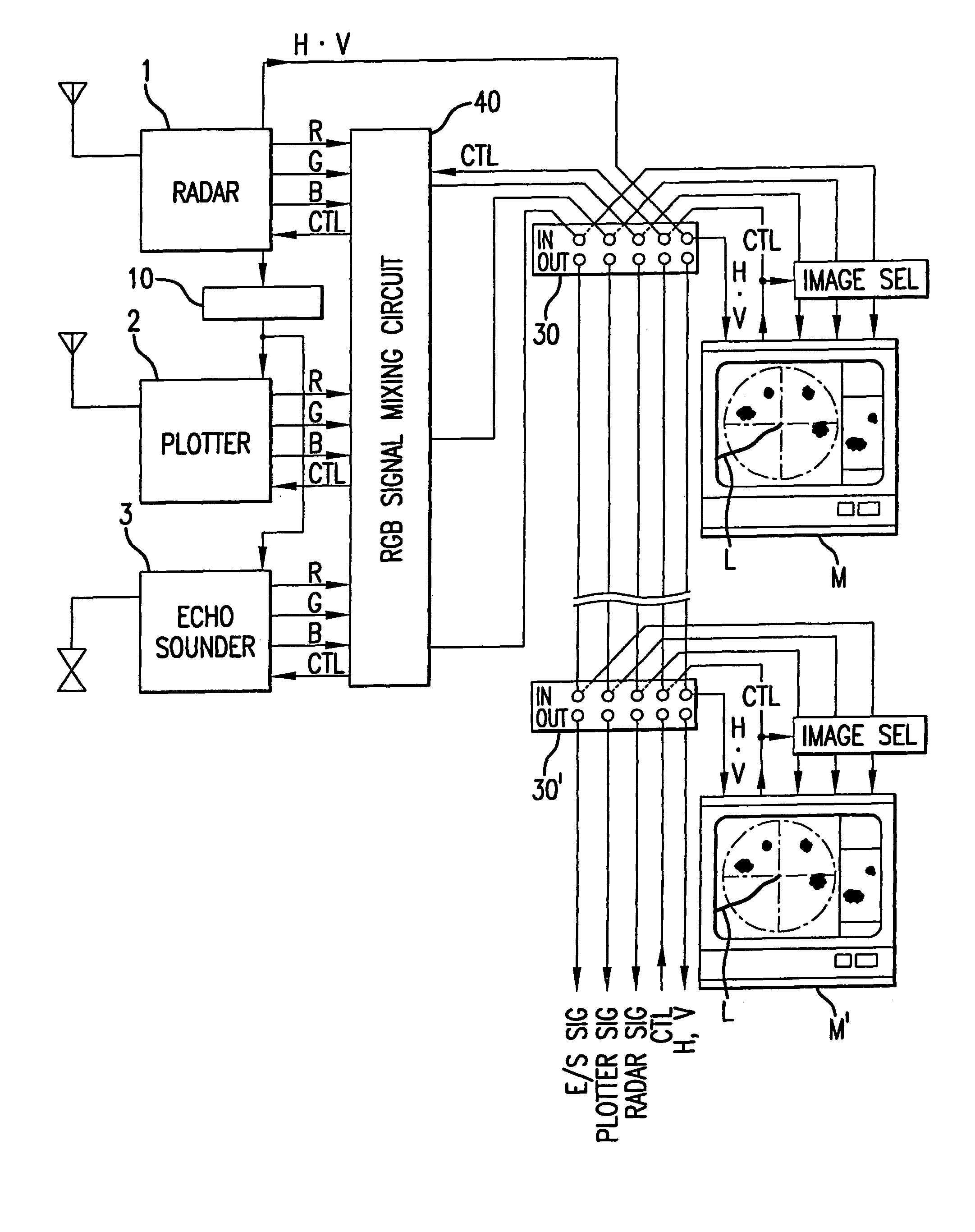
[0055]The display system so far described can present images fed from the individual measuring devices 1–3 in various display modes as shown in FIG. 8 on the indicators M, M′ of FIG. 2 by transmitting the appropriate display control signals to the image selection circuit 20 through the common control line CTL. It is also possible to remotely set the measuring ranges and other operational parameters of the measuring devices 1–3 from the individual indicators M, M′ by transmitting control signals associated with addresses designating the desired destination devices, i.e., the radar 1, the course plotter 2 and the echo sounder 3, as appropriate. While the indicators M, M′ present the same picture in the above-described configuration of FIG. 2, it may be modified to permit presentation of different pictures on the individual indicators M, M′. This is accomplished by a display system according to the invention, which is shown in FIG. 10.

[0056]In the display system of FIG. 10, the indicat...


PUM


Abstract

In a display system capable of displaying images fed from a plurality of sensing devices on an indicator, horizontal and vertical synchronizing signals of the individual measuring devices are synchronized with one another and desired image signals are selected for on-screen presentation during each successive horizontal scanning period, whereby operator-selected multiple images are displayed.

Description

BACKGROUND OF THE INVENTION[0001]The present invention relates generally to an image display system for displaying image information from measuring equipment, such as an echo sounder, and more particularly, the invention is concerned with a display system which can display more than one kind of image information received from a plurality of measuring devices in an integrated manner.[0002]Today's modern fishing vessels and pleasure craft are equipped with a radar 1, a course plotter 2 incorporating, or connected to, a Global Positioning System (GPS) receiver, an echo sounder 3, and so on, as shown in FIG. 1. In a conventional onboard system of this kind, a dedicated indicator M1 is connected to the radar 1 by three signal lines for red (R), green (G) and blue (B) signals, signal lines for horizontal (H) and vertical (V) synchronizing signals. Similarly, an indicator M2 is connected to the course plotter 2 by its R, G and B signal lines and two synchronizing signal lines, while an ind...

Claims


Application Information

Patent Timeline
IPC IPC(8): G09G5/00G01S7/06G01S7/62
CPCG01S7/6218G01S7/06
Inventor KITAYAMA, KENZO
Owner FURUNO ELECTRIC CO LTD
Why Eureka
Try Eureka