
Method and device for optical navigation

a technology of optical navigation and optical compass, applied in the direction of measurement devices, instruments, cathode-ray tube indicators, etc., can solve the problems of typical current optical navigation devices that are dominated by painted metal, and achieve the effects of preserving image quality, enhancing image quality, and improving signal

Inactive Publication Date: 2007-01-09
PIXART IMAGING INC
View PDF21 Cites 60 Cited by
  • Summary
  • Abstract
  • Description
  • Claims
  • Application Information

AI Technical Summary

Benefits of technology

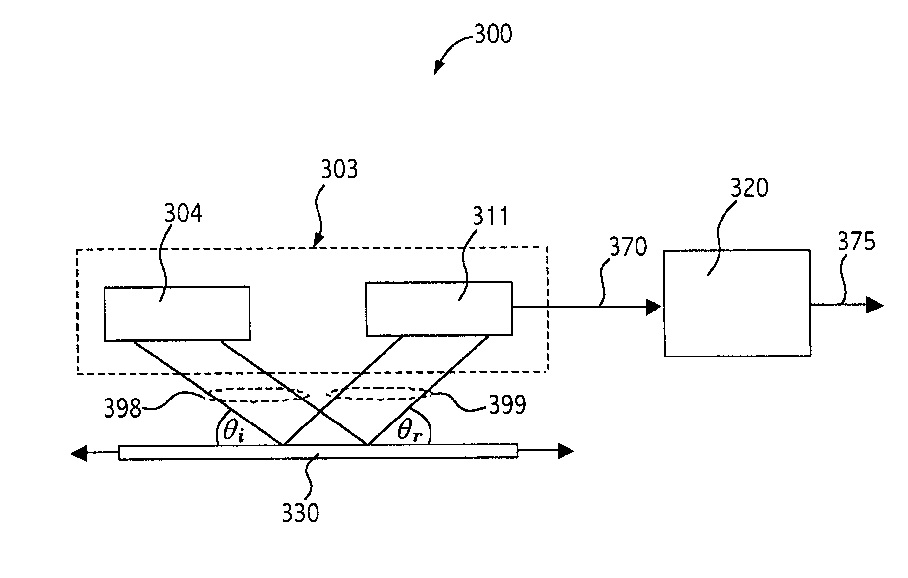
The invention is about a device that uses optical navigation to capture the reflection of light from surfaces. The device uses a detector to capture the reflected light and create high-contrast images even on smooth surfaces. The device can also use a defocused optical configuration to capture images above or below the surface. The use of coherent illumination, such as a vertical cavity surface emitting laser (VCSEL), ensures high-quality specular reflection images for surface navigation.

Problems solved by technology

Smooth surfaces such as whiteboard, high gloss paper, plastic or painted metal present functional challenges to typical current optical navigation devices.

Method used


Image

  • Method and device for optical navigation
  • Method and device for optical navigation
  • Method and device for optical navigation

Examples


Embodiment Construction

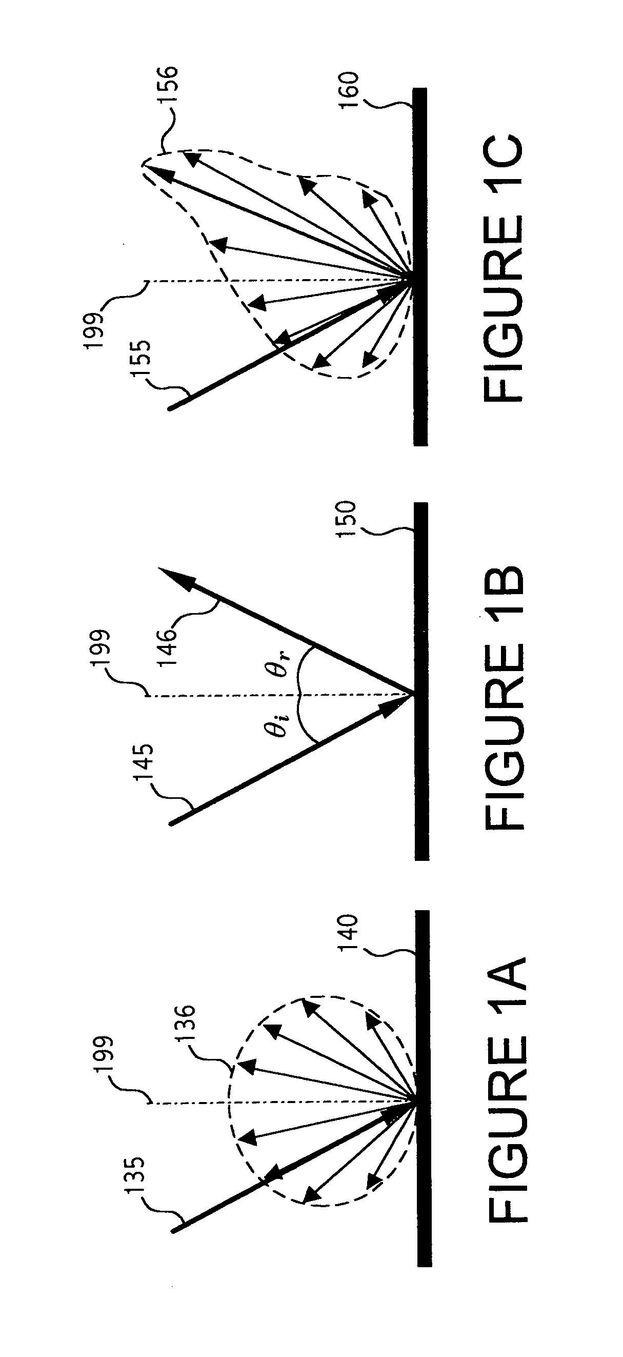
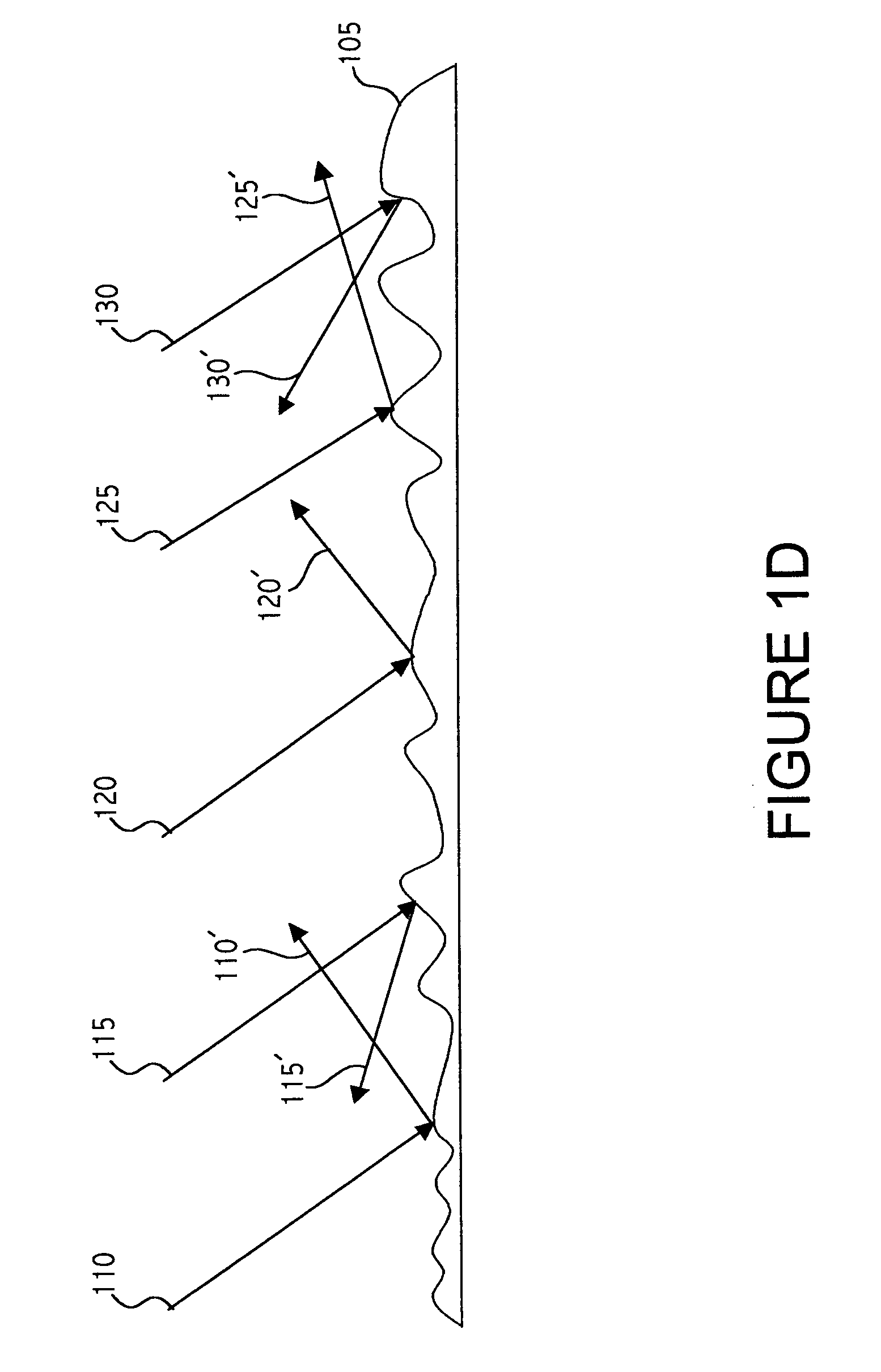
[0022]If a light beam is incident on a smooth surface, the light rays of the incident beam reflect and remain concentrated in a bundle upon leaving the smooth surface. However, if a surface is microscopically rough, then the light rays reflect and scatter in many different directions. The spatial frequency corresponding to the surface roughness may be on the scale of the illumination wavelength. Each individual ray follows the law of reflection. However, in the case of a rough surface each individual ray meets a portion of the surface that has a different orientation. Therefore, the surface normal is different for different incident light rays. Hence, when the individual rays reflect according to the law of reflection, the individual rays scatter in different directions. Furthermore, when either a coherent or a quasi-coherent illumination is applied, high contrast intensity patterns produced by interference among the reflected and the scatter light may be observed in the specular re...


PUM


Abstract

An method and device suitable for navigation on a wide variety of surfaces is introduced. Specular reflection is used to determine relative motion over typical surfaces. A specific application is a computer mouse.

Description

Related Applications[0001]This application is a continuation-in-part of U.S. patent application Ser. No. 10 / 630,169 filed on Jul. 30, 2003.TECHNICAL FIELD[0002]This application relates to motion sensing devices and more particularly to devices, systems and methods for using specular reflection images to determine relative motion.BACKGROUND OF THE INVENTION[0003]Optical relative motion detection devices typically utilize image correlation techniques to determine relative motion between the navigation device and a surface by capturing images of the surface as the navigation device passes over the surface or as the surface moves past the navigation device. Both the displacement and the direction of the relative motion of the navigation device with respect to the surface are determined by comparing one image with the following image. Typically, intensity variations due to shadows cast on the surface are detected and the sensitivity and applicability of this technique depend on the inten...

Claims


Application Information

Patent Timeline
Patent Type & Authority Patents(United States)
IPC IPC(8): G01B9/02G01B11/02G06F3/03G06F3/033
CPCG06F3/0317
Inventor XIE, TONGDEPUE, MARSHALL T.
Owner PIXART IMAGING INC
Learn More