
Systems and methods for the automated sensing of motion in a mobile robot using visual data

a mobile robot and visual data technology, applied in the field of mobile robots, can solve the problems of inability to reliably detect obstacles, high cost, and blind spots of proximity sensors, and achieve the effects of non-uniform shape, poor accuracy, and low cos

Active Publication Date: 2007-01-09
IROBOT CORP
View PDF18 Cites 86 Cited by
  • Summary
  • Abstract
  • Description
  • Claims
  • Application Information

AI Technical Summary

Benefits of technology

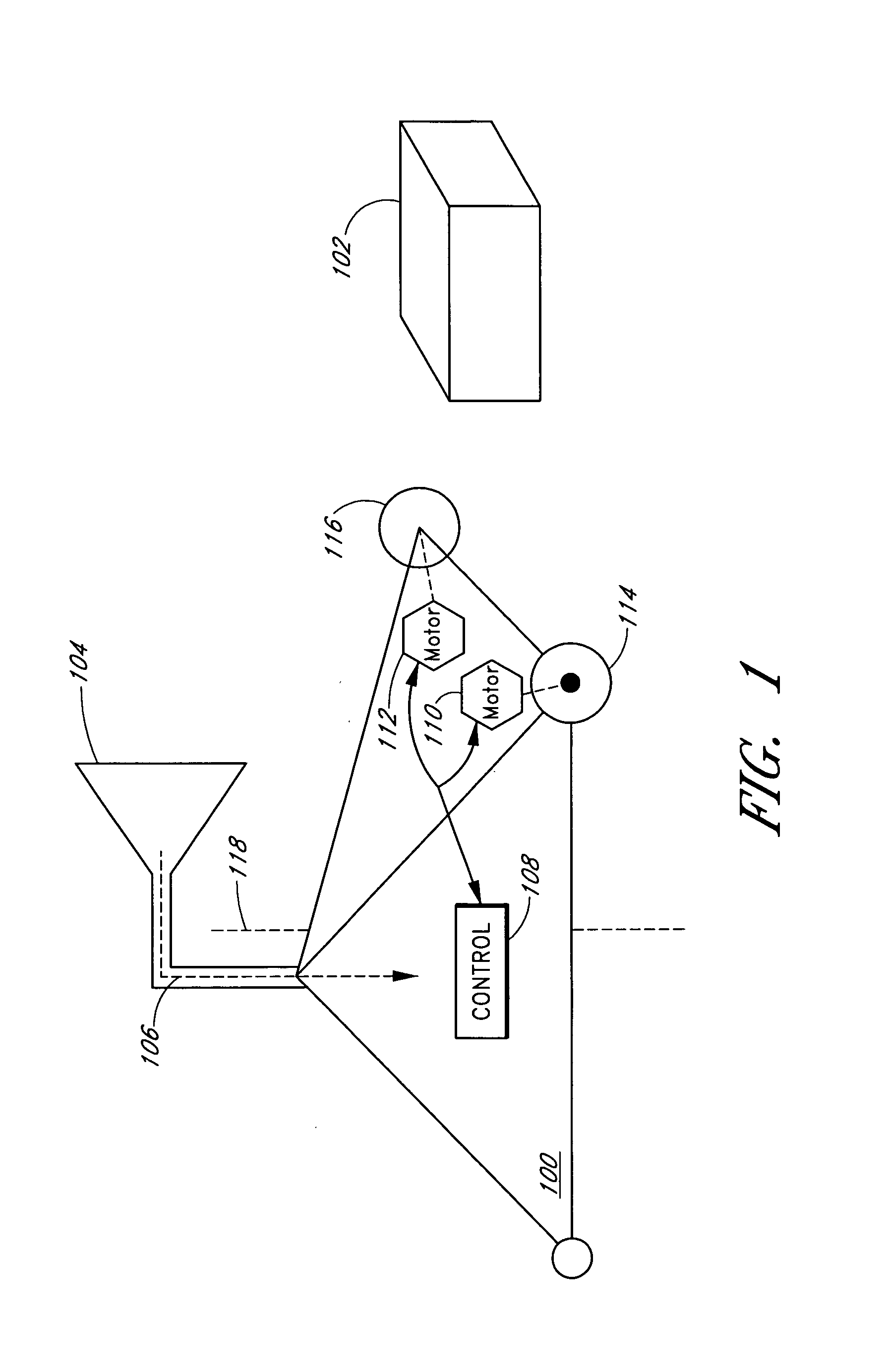
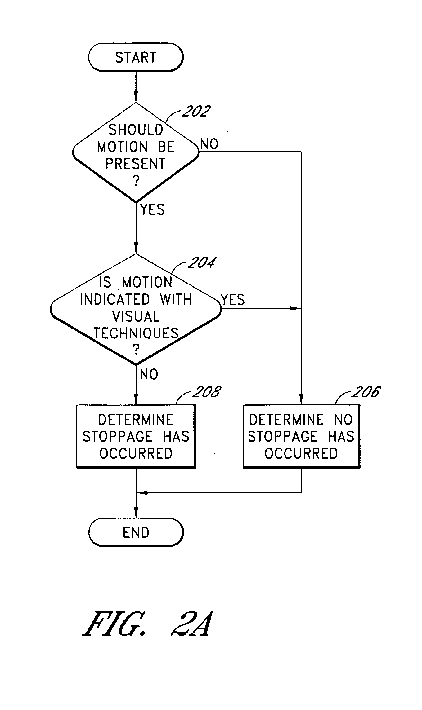
[0018]One embodiment of the invention is a circuit for control of a self-navigating mobile robot, the circuit comprising: a circuit configured to receive an indication that the mobile robot is intended to be traveling in a forward direction; a circuit configured to determine from visual image data collected from a video camera coupled to the mobile robot that the mobile robot has ceased traveling in a forward direction; a circuit configured to discontinue commands to propel the mobile robot in the forward direction; a circu

Problems solved by technology

Disadvantageously however, proximity sensors often do not reliably detect obstacles and can be relatively expensive.
For examples, proximity sensors can suffer from blind spots and can often fail to reliably detect obstructions.
For example, a laser range finder typically performs proximity detection in a single plane such that an obstacle of non-uniform shape, such as an obstacle with a bump or an overhang, may not be reliably detected as an obstacle by the laser range finder.
Disadvantageously however, contact sensors may not reliably detect collisions between the robot and an obstacle.
For example, a bump sensor typically provides coverage for only a relatively small portion of the robot's surface area; thus, an obstacle that contacts the robot outside the coverage area is often undetected by the bump sensor.
In addition, other navigational hazards, such as unnavigable floor surfaces, are typically not detected by the foregoing conventional obstacle detection mechanisms.

Method used


Image

  • Systems and methods for the automated sensing of motion in a mobile robot using visual data
  • Systems and methods for the automated sensing of motion in a mobile robot using visual data
  • Systems and methods for the automated sensing of motion in a mobile robot using visual data

Examples


Embodiment Construction

[0036]Although this invention will be described in terms of certain preferred embodiments, other embodiments that are apparent to those of ordinary skill in the art, including embodiments that do not provide all of the benefits and features set forth herein, are also within the scope of this invention.

[0037]It will be understood by one of ordinary skill in the art that mobile robots can be embodied in a variety of forms. In these variety of forms, a robot may be referred to by a different name, such as by a function that is performed by the robot. For example, a robot may be referred to as an automated sweeper or as an automated vacuum cleaner. In one embodiment, a mobile robot corresponds to a self-propelled object that can navigate in an autonomous or semi-autonomous manner. Examples of autonomous or semi-autonomous mobile robots include, but are not limited to, mobile robots for use in automated floor cleaners, humanoid robots, robots for experimentation and lab use, robots for d...


PUM


Abstract

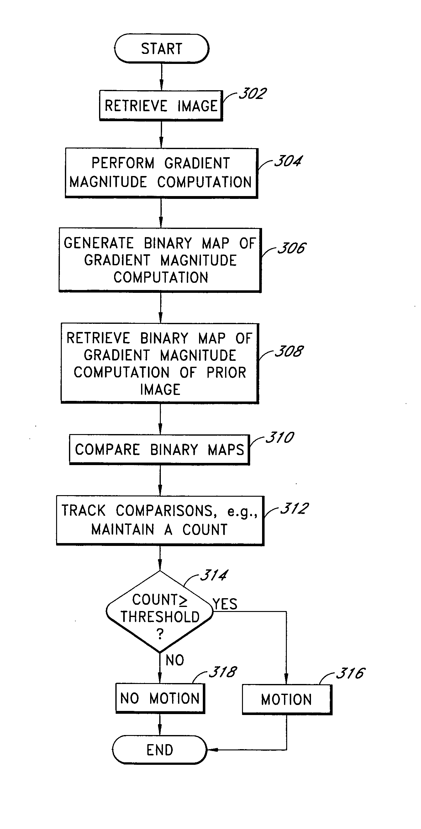
The invention is related to methods and apparatus that detect motion by monitoring images from a video camera mounted on a mobile robot, such as an autonomously navigated mobile robot. Examples of such robots include automated vacuum floor sweepers. Advantageously, embodiments of the invention can automatically sense a robot's motional state in a relatively reliable and cost-efficient manner. Many configurations of robots are configured to include at least one video camera. Embodiments of the invention permit the use of a video camera onboard a robot to determine a motional state for the robot. This can advantageously permit the motional state of a robot to be determined at a fraction of the cost of additional sensors, such as a laser, an infrared, an ultrasonic, or a contact sensor.

Description

RELATED APPLICATION[0001]This application claims the benefit under 35 U.S.C. § 119(e) of U.S. Provisional Application No. 60 / 404,348, filed Aug. 16, 2002, the entirety of which is hereby incorporated by reference.BACKGROUND OF THE INVENTION[0002]1. Field of the Invention[0003]The invention generally relates to mobile robots. In particular, the invention relates to a relatively economical and efficient technique to permit a mobile robot to detect a motional state.[0004]2. Description of the Related Art[0005]Mobile robots are becoming more and more commonplace in society. It will be understood that these robots can be embodied in various forms, such as in automated vacuum cleaners. A variety of applications can be found for mobile robots, such as, but not limited to, entertainment applications, such as toy robots, utility applications in environments that are unfriendly to humans, such as space, deep water, cold temperature, radiation, chemical exposure, biohazards, etc., dangerous ta...

Claims


Application Information

Patent Timeline
IPC IPC(8): G06K9/00G05B15/00H04N7/00B25J5/00B64C13/18G01C22/00B25JG05D1/02G06T7/20
CPCG05D1/0246G06T7/2033G05D1/0253G05D1/0227G05D1/024G05D1/0242G05D1/0255G05D1/0272G05D1/0274G05D2201/0215G06T7/246
Inventor BURL, MICHAEL CHRISTOPHERPIRJANIAN, PAOLO
Owner IROBOT CORP
Learn More