Non-circular, mechanically variable optical attenuator

a mechanically variable, optical attenuator technology, applied in the direction of optical elements, optical radiation measurement, instruments, etc., can solve the problems of increasing optical attenuation, difficult to achieve circular mechanical motion required for crossing polarizers, and inability to rotate, etc., to achieve easy control

Inactive Publication Date: 2007-01-09
WEST VIRGINIA UNIVERSITY
View PDF15 Cites 21 Cited by
  • Summary
  • Abstract
  • Description
  • Claims
  • Application Information

AI Technical Summary

Benefits of technology

[0020]Accordingly, in solving the problems associated with the prior art, it is an aspect of the present invention to provide for a not exclusively circular, but arbitrarily shaped (depending on application needs), Mechanically Variable Optical Attenuator with application for dimmable mirrors and transmissive applications such as window glass by providing a variable optical attenuator that is purely mechanical. The disclosed invention consists of using a pair of specially constructed polarizing elements with means enabling a gradual transition from un-crossed polarization vector fields to crossed polarization vector fields using a linear motion with respect to one another in place of circular motion. This is achieved through polarizing elements whose polarization axis varies with spatial position on the element thereby comprising a polarization vector field that is a function of position on the element. Rather than using the conventional terminology of a single polarization axis f

Problems solved by technology

One common configuration of a mechanical variable optical attenuator involves a pair of polarizers which are gradually misaligned (or crossed) through rotation of one of the polarizers with respect to the other, leading to increasing optical attenuation.
The circular mechanical motion required for crossing polarizers is not always easily achievable due to mechanical constraints.
In an application, such as dimming of side and rear view mirrors on a vehicle for glare reduction, rotation is not practical as most of these mirrors are not circular in shape.
The use of liquid crystal attenuators in this application is problematic as the liquid crystals are susceptible to damage from the environment such as UV radia

Method used


Image

  • Non-circular, mechanically variable optical attenuator
  • Non-circular, mechanically variable optical attenuator
  • Non-circular, mechanically variable optical attenuator

Examples


Embodiment Construction

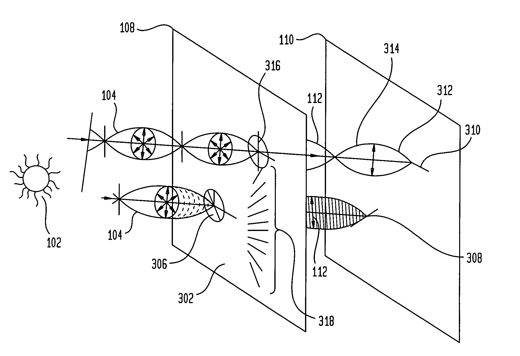
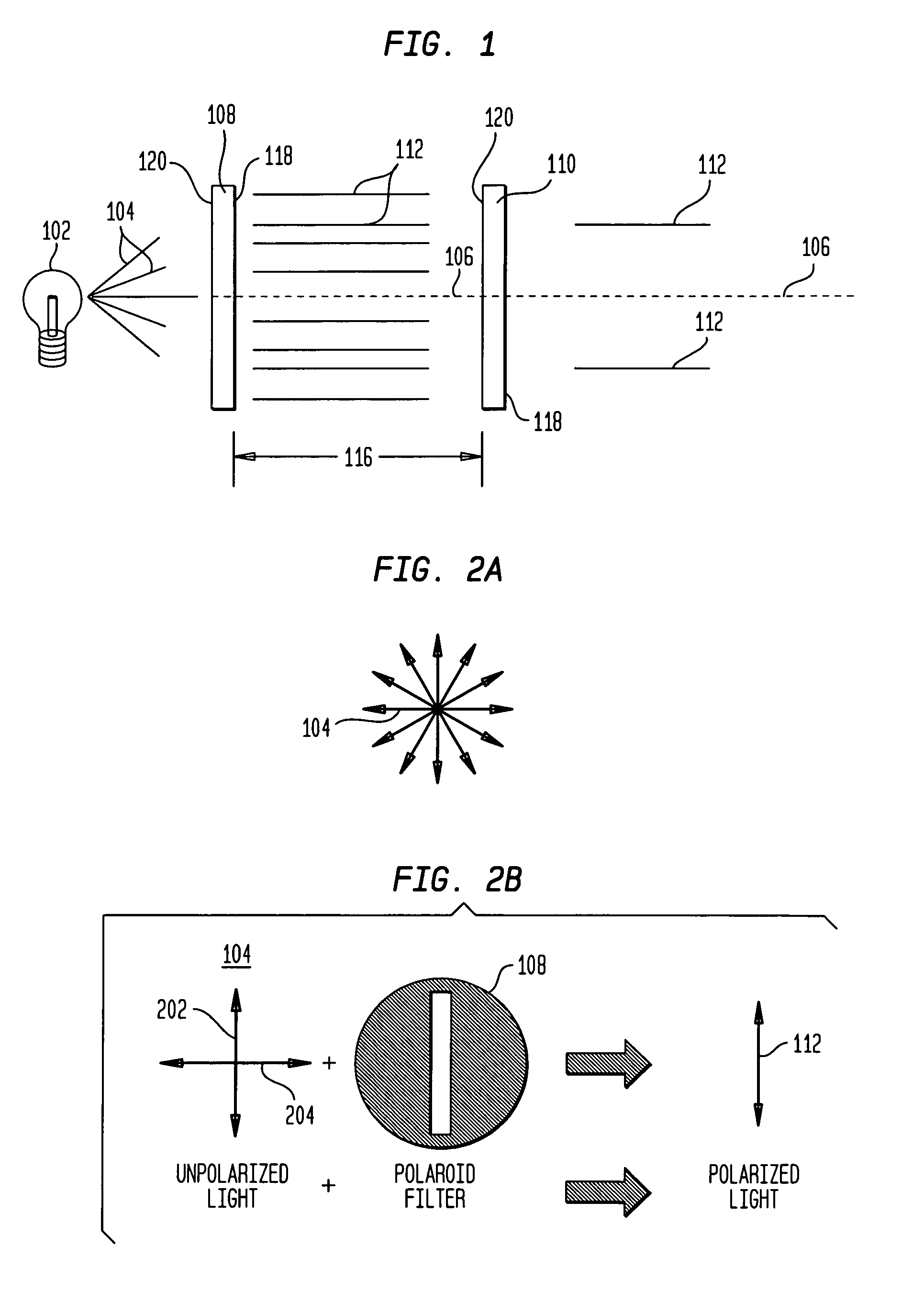
[0042]Preferred embodiments of the present invention are described below in detail with reference to the accompanying drawings. Referring more particularly to FIG. 1, white light 104, from a light source 102, is shown. It would be readily apparent to one skilled in the art that other forms of light, such as monochromatic light, single frequency light, as well as polychromatic light could be readily applied to the invention herein described and are alternative embodiments of the invention and that white light 104 is used for the purpose of convenience only. Additionally, it would be equally apparent to one skilled in the art that other forms of electromagnetic radiation including infrared radiation, ultra-violet radiation, and radio waves in addition to visible light are alternative embodiments of the present invention.

[0043]FIG. 1 illustrates white light 104 traveling through a first polarizing element 108 and a second polarizing element 110 along a propagation axis 106. Polarized l...


PUM


Abstract

A non-circular, mechanically variable optical attenuator using a pair of specially constructed polarizing elements with means enabling a gradual transition from un-crossed polarization vector fields to crossed polarization vector fields using a linear motion with respect to one another. The polarizing elements whose polarization axis varies with spatial position on the element have a polarization vector field that is a function of position on the element. Specifically, the two polarizing elements have a defined orientation of polarization axes or vectors on the polarization vector fields that vary with spatial location on the polarizing element such that when aligned light passes, and when the polarization axes are crossed, light is attenuated. The present attenuator has a practical application for dimmable mirrors or windows by providing a variable optical attenuator that is purely mechanical and non-circular in shape. Dimming of the mirror or window is controlled by gradually sliding one such special polarizer with respect to the other.

Description

BACKGROUND OF THE INVENTION[0001]1. Field of Invention[0002]This invention relates to a non-circular mechanically variable optical attenuator using a pair of specially constructed polarizing elements to achieve a smooth transition from un-crossed to crossed polarized vector fields using a linear motion with respect to one another in place of circular motion. More specifically, the present invention uses mechanical translation and two non liquid polarizing elements through which light can pass with spatially varying polarization axes to achieve variable attenuation.[0003]2. Related Art[0004]In order to obtain a continuously variable optical attenuator, various methods can be used. One such method is to use polarizers. It is generally known in the art that a polarizer refers to a polarizing filter that has two transparent surfaces similar to a glass lens and other optical elements. Electrical and mechanical means for controlling the degree of attenuation through misalignment of the po...

Claims


Application Information

Patent Timeline
IPC IPC(8): G02B6/00
CPCG01J1/04G01J1/0418G01J1/0429G02B26/02G02B5/3025G01J1/0488G02B6/266G02B6/276G02B6/3594G01J2001/0276
Inventor PERTL, FRANZ ANDREAS JOHANNESNASSAUER, FREDERICK J.SMITH, JAMES E.
Owner WEST VIRGINIA UNIVERSITY
Why Eureka
Try Eureka