Non-slip material

a non-slip material and stopper technology, applied in the field of stoppers, can solve the problems of increasing production processes and costs, affecting the effect of cleaning, and causing noise escape, and achieve the effect of increasing the stopper

Inactive Publication Date: 2007-01-16
SHIN CATERPILLAR MITSUBISHI LTD CORP
View PDF30 Cites 13 Cited by
  • Summary
  • Abstract
  • Description
  • Claims
  • Application Information

AI Technical Summary

Benefits of technology

[0007]This structure shows a great slip stopping effect, and provides a slip stopper that can also be used for a location which may pose a problem if a through hole is opened therein.
[0008]In this structure, the protruding portion can be formed to have a mountain shape that becomes high at the central portion and lowers toward the marginal section and has a roughly arc-shaped section, and, for example, the concave portion can be formed at the central portion of the protruding portion by using the shear planes as inner circumferential surfaces. Furthermore, by forming drain channels shaped into concave grooves leading to the plate surface of the metal plate from the concave portion, the slip stopping effect can be prevented from being lost due to the accumulation of water or dirt in the concave portion.
[0009]In this structure, the drain channels are radially formed in a plurality from the concave portion. Further, the slip stopping effect can be increased by forming the channel side surfaces of the drain channels by shear planes which face perpendicularly to the plate surface of the metal plate and are obtained by half blanking that does not open a through hole in the metal plate.

Problems solved by technology

If the slip stopper having the through hole stamped out is used as it is as, for example, for a cover to cover the upper surface of a construction machine, problems such that rainwater or dirt enters the inside of the cover, heated air from an engine blows upward from the cover, or noise escape are inevitable.
However, the double structure increases production processes and costs in comparison with the single structure, and further poses a problem in that mud or dust entering the through hole of the slip stopper accumulates between the slip stopper and the lower side flat steel plate or collects in the through hole, and makes cleaning difficult.

Method used


Image

  • Non-slip material
  • Non-slip material
  • Non-slip material

Examples


Embodiment Construction

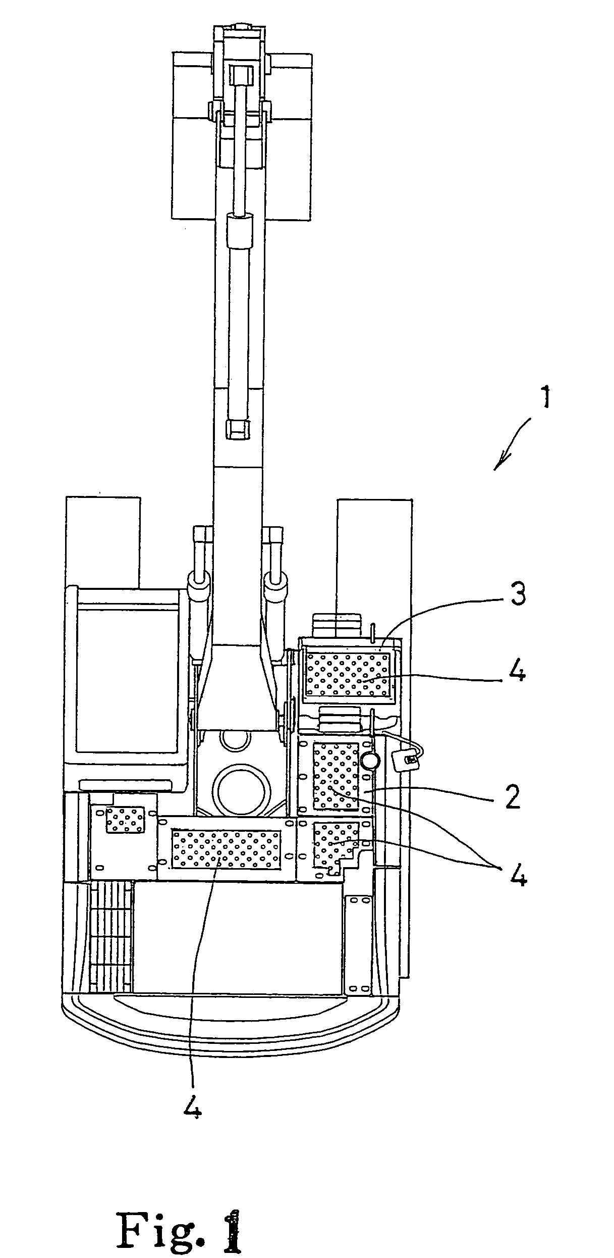
[0025]In the drawings, 1 denotes a construction machine (hydraulic excavator), and the construction machine is constructed so that the upper surfaces of a cover 2 covering the machine upper surface and a tool box 3 are formed as stepping surfaces on which a worker can walk or step during maintenance, and a slip stopper 4 to which the disclosure is applied is for these stepping surfaces.

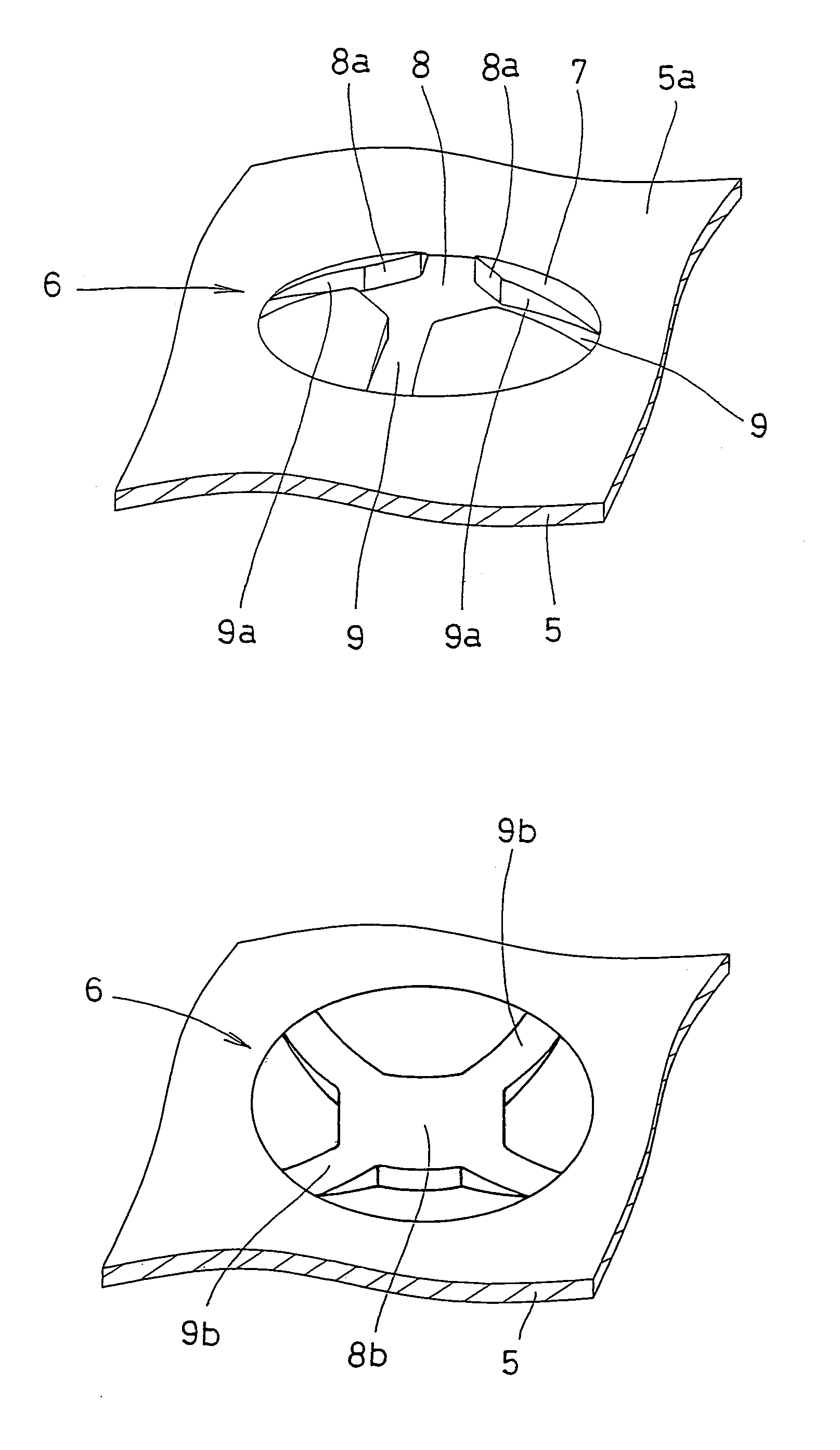
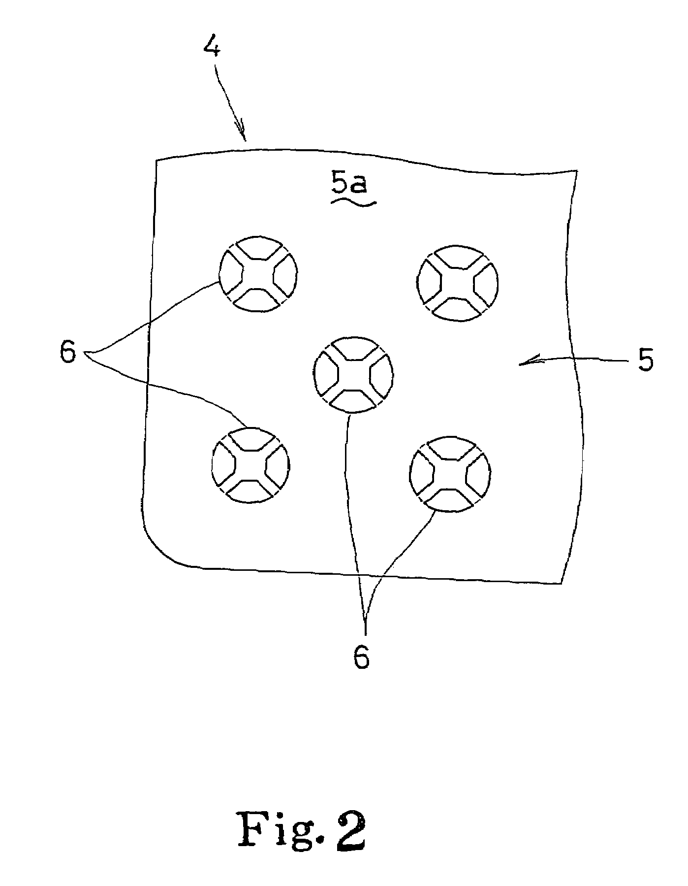
[0026]The slip stopper 4 (FIG. 2) is formed by forming a plurality of slip stopping parts 6 in a vertically and horizontally running pattern on a flat steel plate 5. Each slip stopping part 6 (as shown in FIGS. 3(A)–3(C)) has a concave portion 8 and drain channels 9 formed by shear planes 8a, 9a, described later, in the protruding portion 7 that protrudes in the plate thickness direction from the upper surface 5a of the steel plate 5.

[0027]Namely, the protruding portion 7 is shaped to be circular in a plan view and have a roughly arc-shaped section, a roughly quadrilateral concave portion 8 is formed ...


PUM

PropertyMeasurementUnit
heightaaaaaaaaaa
thicknessaaaaaaaaaa
anglesaaaaaaaaaa

Abstract

The invention provides a slip stopper which achieves a great slip stopping effect, and can be used for a location where a problem occurs if a through hole is opened therein. In a protruding portion that protrudes from the upper surface of a steel plate in the plate thickness direction, a concave portion and drain channels, that lead to the steel plate upper surface from the concave portion, are formed. The inner surface of the concave portion and the groove side surfaces of drain channels are formed by shear planes which extend substantially perpendicular to the steel plate upper surface, and are obtained by half blanking that does not open a through hole in the steel plate.

Description

[0001]This application claims priority from JP 2002-002650 filed Jan. 9, 2002, through PCT / JP02 / 11740 filed Nov. 11, 2002. The material found in both documents is incorporated herein by reference thereto.TECHNICAL FIELD[0002]The invention relates to the technical fields of a slip stopper employed for stepping surfaces of floors, passageways, and steps, etc., provided in building structures and construction machines.BACKGROUND ART[0003]Generally, a slip stopper with a slip stopping function is occasionally used for floors, passageways, and stairs in building structures, floors and steps of buses, trucks and special vehicles, decks of railroad vehicles and ships, and scaffolding at construction sites. Such a slip stopper, for example, a slip stopper as shown in FIGS. 12(A)–12(C), has been conventionally known. This is a so-called striped steel plate, the steel plate has a plurality of projections 10 molded in a continuous patterned shape. A corresponding slip stopping effect can be ex...

Claims


Application Information

Patent Timeline
Patent Type & Authority Patents(United States)
IPC IPC(8): E01C11/24B21D22/04B21D28/10E02F9/16E02F9/24E04F11/02E04F11/112E04F11/16E04F15/02E04F15/06E04G5/08
CPCB21D22/04E02F9/16E04F11/112E04F15/02E04F15/06E04F11/16Y10T428/12368E04F15/02172
Inventor OHNO, SHUNJIIWASA, KAZUMICHINAKAJIMA, NORIOTSUJI, MASANORIDOI, TSUYOSHIKOUZU, YOSHIHISAAGARIHAMA, YOSHIHIROURA, SHINYAMIYAKE, HIDEYUKI
Owner SHIN CATERPILLAR MITSUBISHI LTD CORP
Why Eureka
Try Eureka