[0005]The object of the present invention is to overcome the abovementioned disadvantages at least partially, or to provide a useful alternative, and in particular to provide a compact filling device that is flexible in use, with an optimized
processing functionality. More particularly, the object of the invention is to provide a filling device by means of which it is possible in a partially aseptic area still to fill and close containers under aseptic conditions.
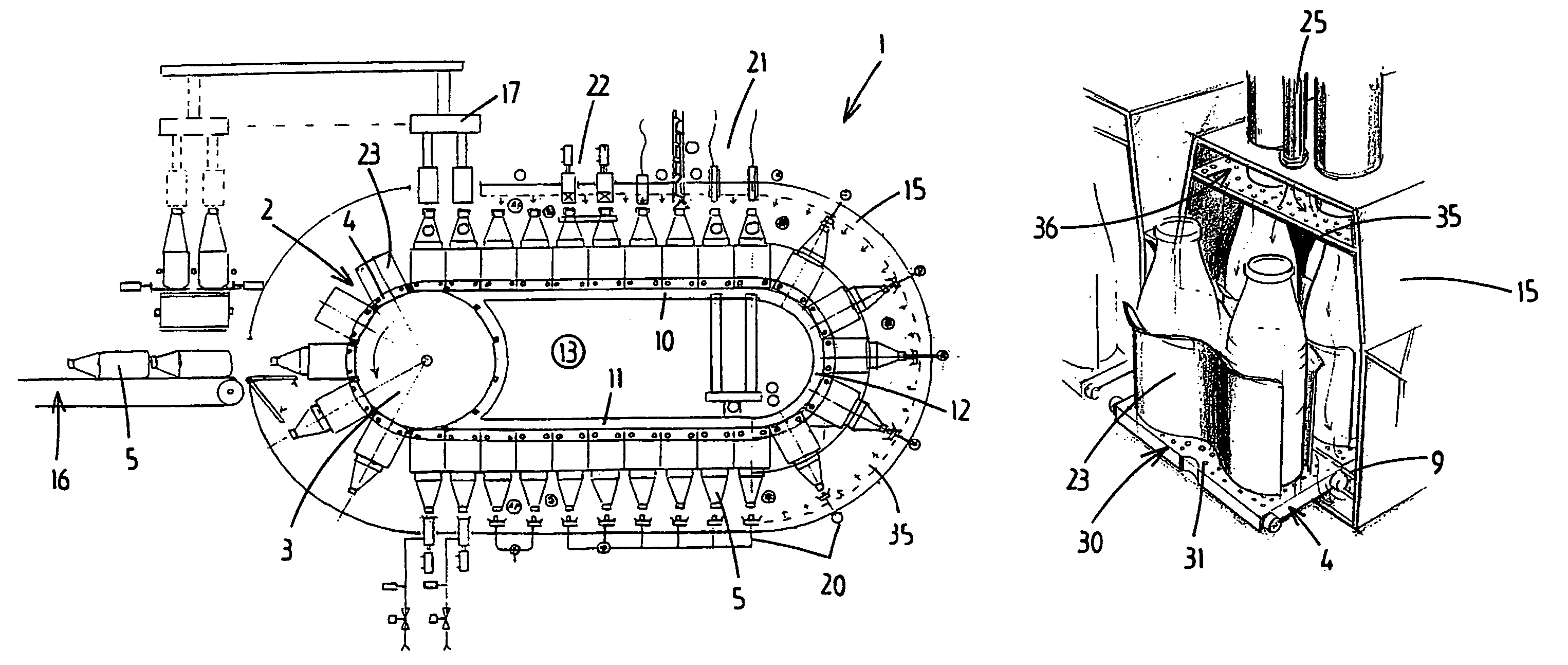
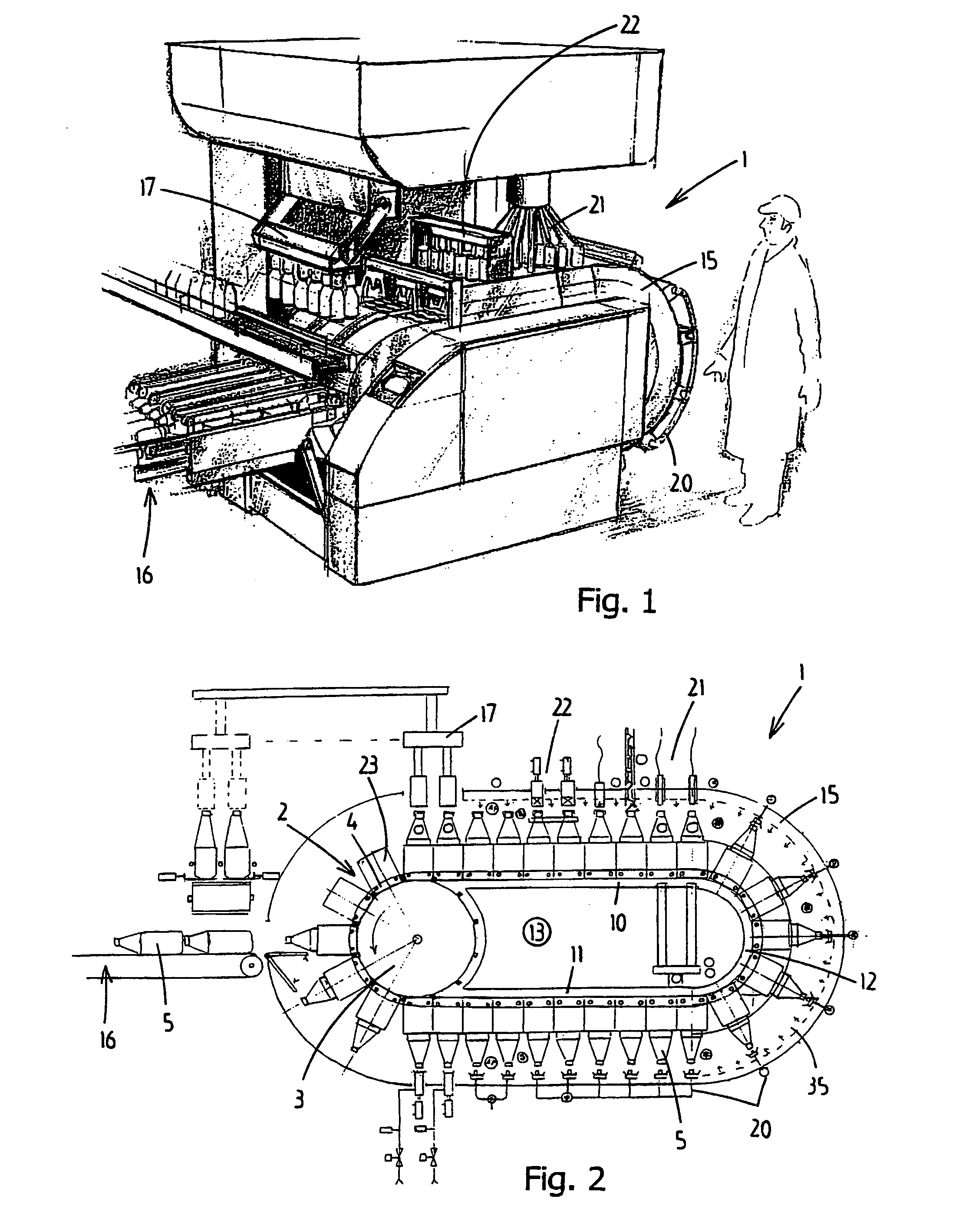
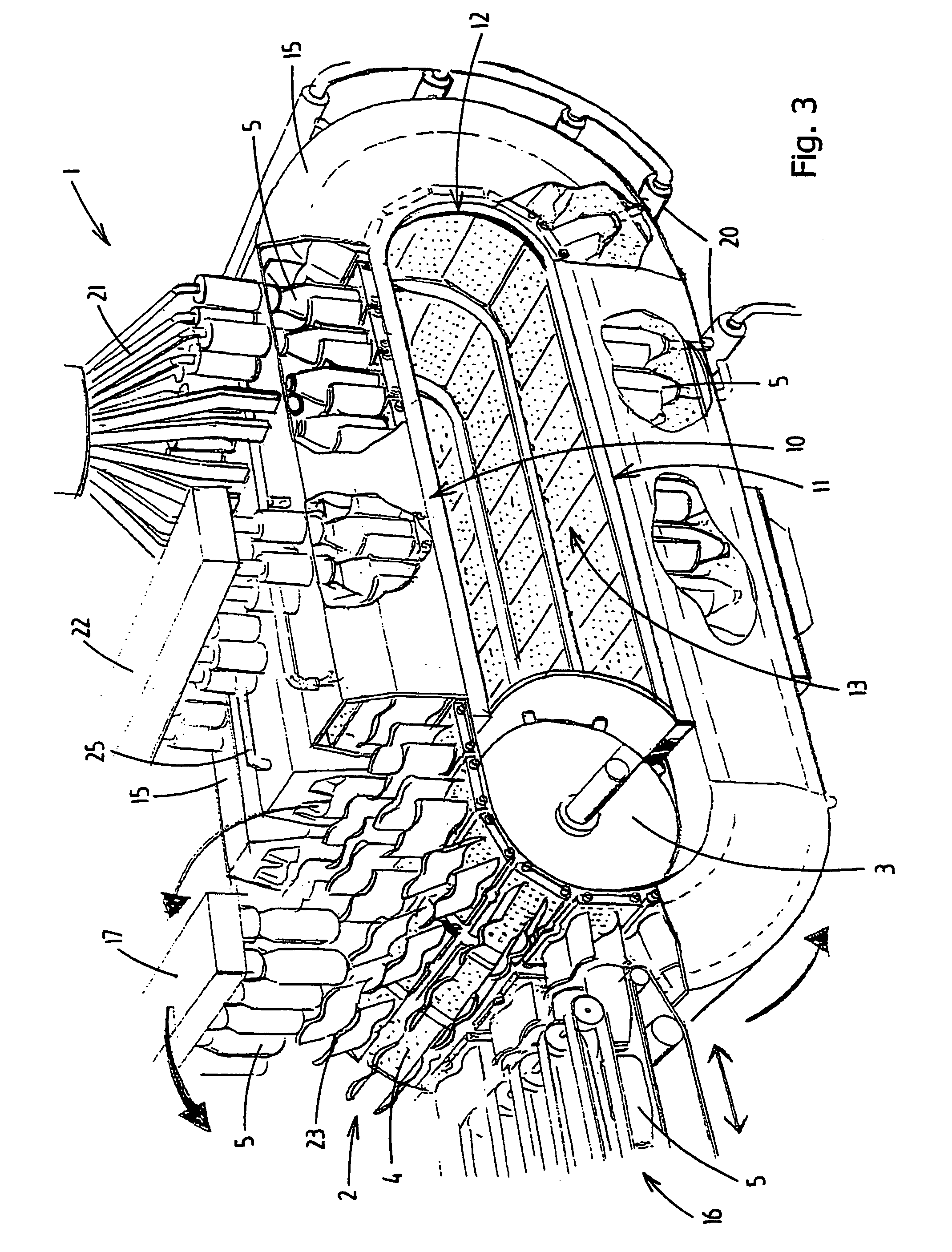
[0006]This object is achieved by a filling device according to the present invention. In this case, a housing is provided along the processing line, which housing extends at least along the filling station and the closing station. Inside the housing gas supply means are disposed for substantially close to filling apertures make the gases flow along outsides of containers being conveyed along said housing, in the direction of bottoms of said containers. The gas supply means comprise a plurality of gas outflow apertures, in particular a large number disposed at intervals and opening into the housing. The number of the gas outflow apertures and their arrangement here are such that for substantially each conveyance position of a container along the housing, at least one of the gas outflow apertures is situated at a distance of less than 25 centimetres, in particular less than 15 centimetres, from the corresponding container filling aperture. This means that from the moment the containers are cleaned until the moment they are closed the filling apertures are situated at a
short distance below the gas supply. The path taken by the gas from the gas outflow apertures to the filling apertures is consequently also short, with the result that the risk of
pollution of the gases by polluted
machine surfaces and / or mixing with polluted air is minimal. A substantially uniform flow of conditioned gases can therefore advantageously be achieved for each conveyance position of a container along the housing, in this case the introduced gases flowing in succession first along the filling apertures of the containers to be filled, and only then along the remainder of the outsides of the containers and parts of the
conveyor system. Such a directed, substantially uniform flow of the conditioned gases prevents the spread of pollutants at the position of at least the filling apertures of individual containers. Furthermore, it is ensured that the most critical points during the filling process, i.e. the environment around the filling apertures of the containers during filling and closing, will not undesirably become polluted by
dirt coming from the remainder of the outside of the container, or
dirt coming from
moving parts of the
conveyor system. This advantageously also means that less high standards need be set for the cleanness of the outsides of the containers. For example, these outsides need no longer be made fully sterile, which produces both a
gain in time and a cost saving.
[0007]The invention therefore makes it possible to keep the area around the processing line at the position of the housing only partially clean in a conditioned manner, in particular aseptic, while the filling and closing of the containers can still be performed in a reliable manner under the generally required aseptic conditions.
[0011]In particular, the housing is made at least partially tunnel-shaped, at least the part of the processing line that faces outwards being covered over. The covering leaves free a tunnel through which the containers to be filled can be conveyed along the stations. This gives the
advantage that the area that has to be kept under certain processing conditions during operation, in particular the environment surrounding the filling apertures of the containers, is minimized. The number of parts, and also the surface area of these parts that is situated inside the housing, can also advantageously be minimized. The quantity of conditioned gases required is advantageously small.
[0013]According to the invention, individual processing conditions can advantageously prevail within each housing segment, for example the supply of different gases, the temperature,
sterility,
humidity etc. If one of the processing lines becomes polluted, this advantageously does not directly have the consequence that the other processing lines become polluted. If there is a fault in one of the processing lines, the device may, if desired, continue to operate for the other processing lines. The individual housing segments also make it possible expediently further to reduce the working area in which the filling operations have to be carried out, so that the desired processing conditions can be achieved and maintained in a simpler manner.

