Pneumatic distribution system for air seeders

a technology of pneumatic distribution system and air seeder, which is applied in the direction of potato planter, volume/mass flow by differential pressure, sowing, etc., can solve the problems of insufficient airflow, product falling from the stream and beginning to build up on the bottom, and loss of kinetic energy, etc., to achieve the effect of minimal maintenan

US7162962B2Active Publication Date: 2007-01-16MORRIS EQUIP LTD
13 Cites 50 Cited by

Patent Information

Authority / Receiving Office
US · United States
Patent Type
Patents(United States)
Current Assignee / Owner
Publication Date
2007-01-16

Smart Images

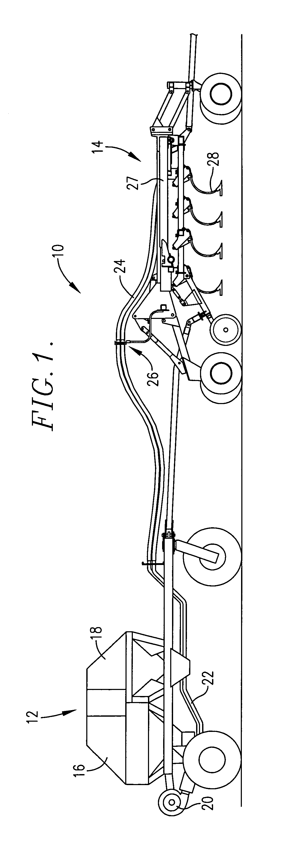
  • Figure 1
    Figure 1
  • Figure 2
    Figure 2
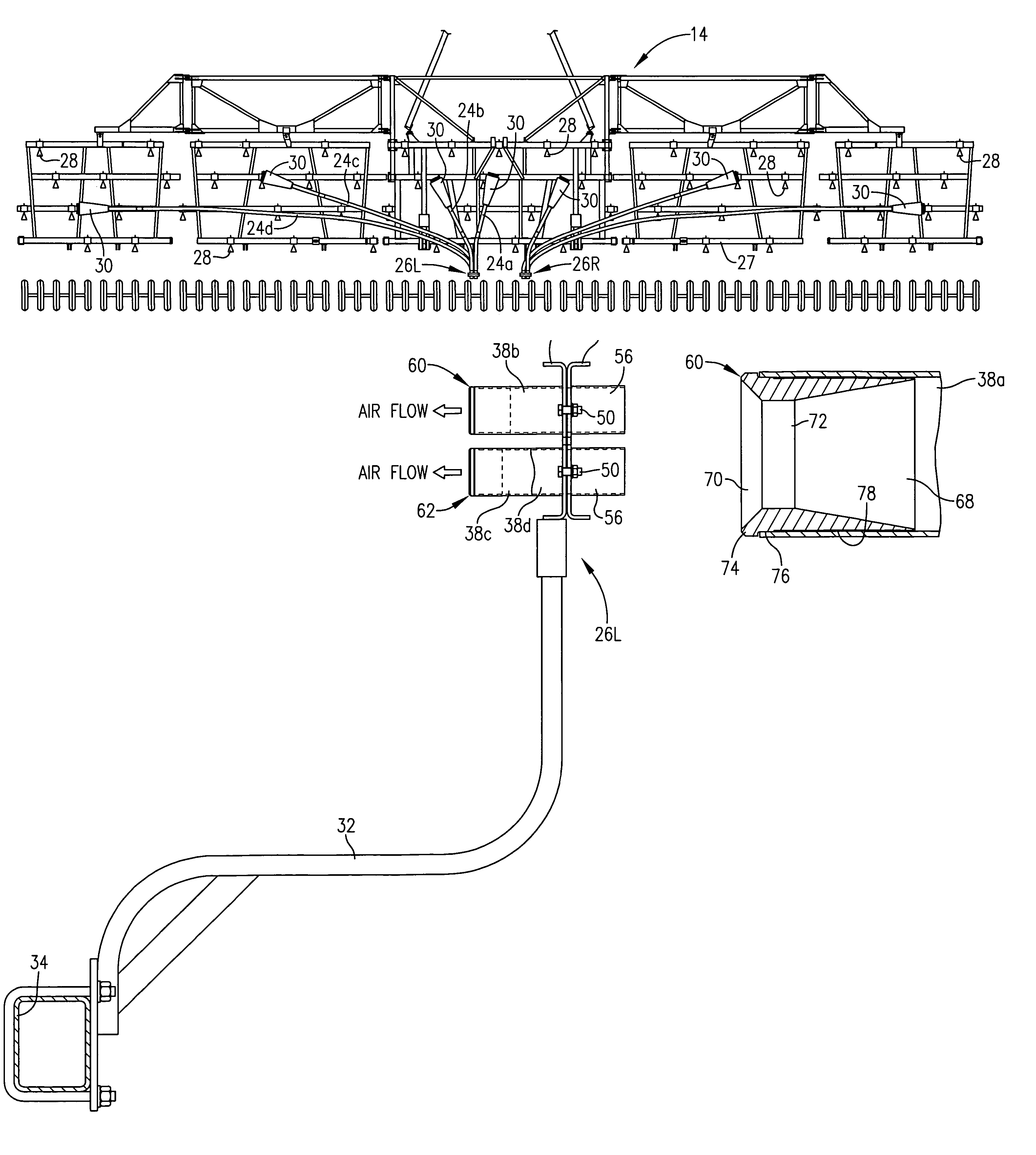
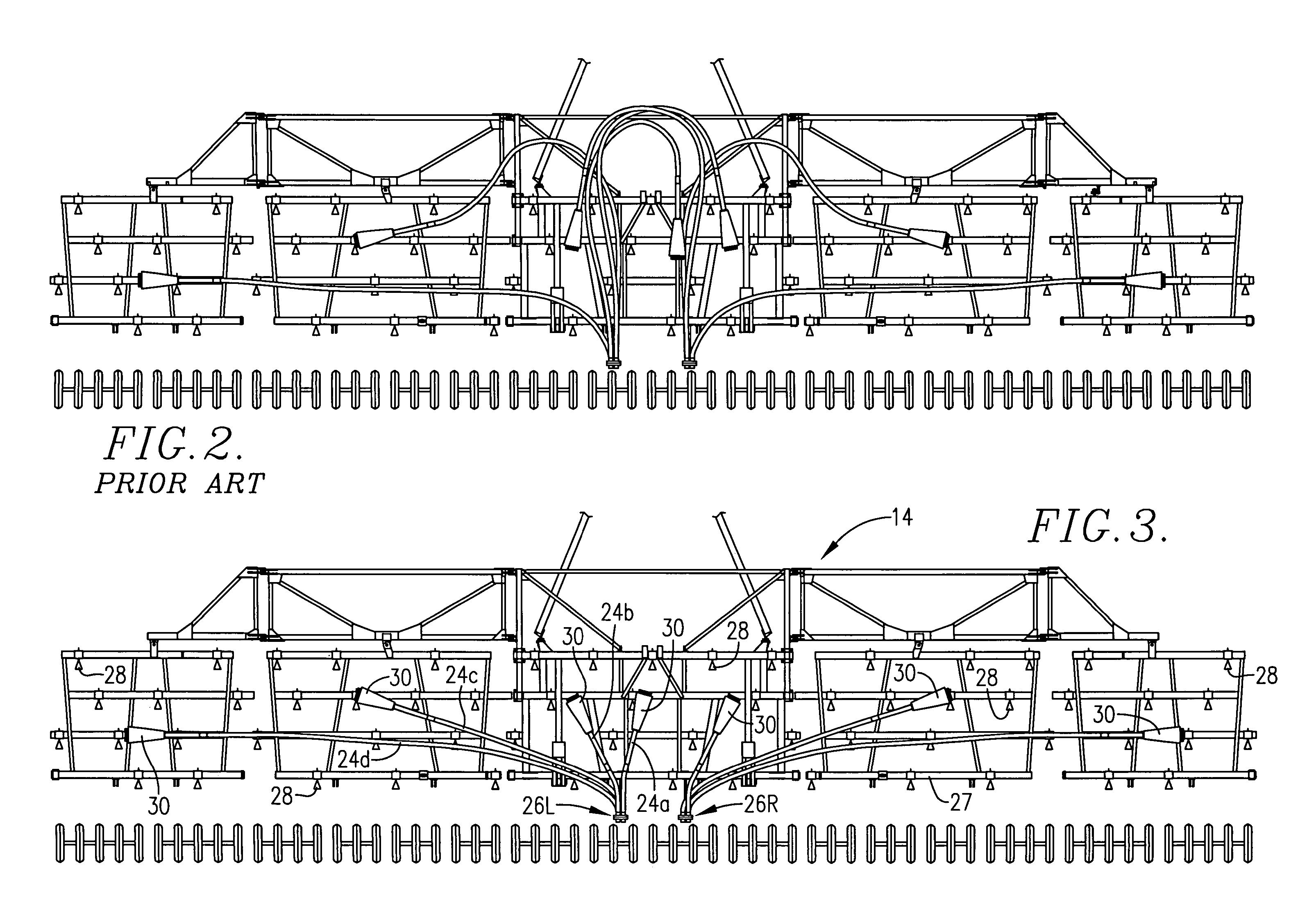
  • Figure 3
    Figure 3
Patent Text Reader

Abstract

The primary distribution hoses on the tillage implement of a pneumatic seeding machine are of different lengths as needed to reach distribution heads or splitters on the implement that further divide the primary streams of materials into individual streams leading directly to the ground-engaging openers of the implement. Notwithstanding the differential in hose length, outlet pressures at the distribution heads are made uniform through the provision of internal flow restrictors associated with those hoses that are shorter than the longest hoses on the machine. Throat diameters of the restrictors vary in accordance with the pressure drop that is needed to match the difference in hose length between the longest hose and the restricted hose. In a preferred embodiment, the restrictors are mounted within nipples on the coupling assembly that releasably connects conduits from a seed cart with the primary hoses on the implement.
Need to check novelty before this filing date? Find Prior Art

Description

TECHNICAL FIELD

[0001] The present invention relates to pneumatic seeding machines typically referred to as “air seeders” and, more particularly, to a way of achieving uniform delivery of seeds to all destination points on the machine, notwithstanding the fact that such points are located at a variety of different distances from the common source of airflow.BACKGROUND AND SUMMARY

[0002] As air flows through a duct, such as a tube or hose, it loses kinetic energy, in the form of pressure, due to friction. Such pressure drop is a function of a number of different factors, including the shape and size of the duct and its length.

[0003] In an air seeder utilizing a pneumatic conveyance system, the success of the system is dependent upon maintaining an adequate amount of airflow throughout the system to keep the seeds in suspension within the air stream. If the airflow is insufficient, the product will fall from the stream and begin to build up on the bottom of the tube or hose. If the conditi...

Examples

Embodiment Construction

[0017]The present invention is susceptible of embodiment in many different forms. While the drawings illustrate and the specification describes certain preferred embodiments of the invention, it is to be understood that such disclosure is by way of example only. There is no intent to limit the principles of the present invention to the particular disclosed embodiments.

[0018]The seeding machine 10 shown in FIG. 1 includes a mobile cart 12 containing a supply of seeds and / or fertilizer, and a planting implement 14 which is supplied seeds by cart 12. Cart 12 and implement 14 are adapted to be towed by a tractor (not shown) so that the seeds and / or fertilizer may be deposited into the ground as the machine is advanced across the field by the tractor. Although the implement 14 has been illustrated in a leading relationship with the cart 12, the order of appearance could be reversed with the cart being connected directly to the tractor and the implement 14 being towed by the cart.

[0019]As...