
Engine braking methods and apparatus

Active Publication Date: 2007-01-16
JACOBS VEHICLE SYST
View PDF18 Cites 35 Cited by
  • Summary
  • Abstract
  • Description
  • Claims
  • Application Information

AI Technical Summary

Benefits of technology

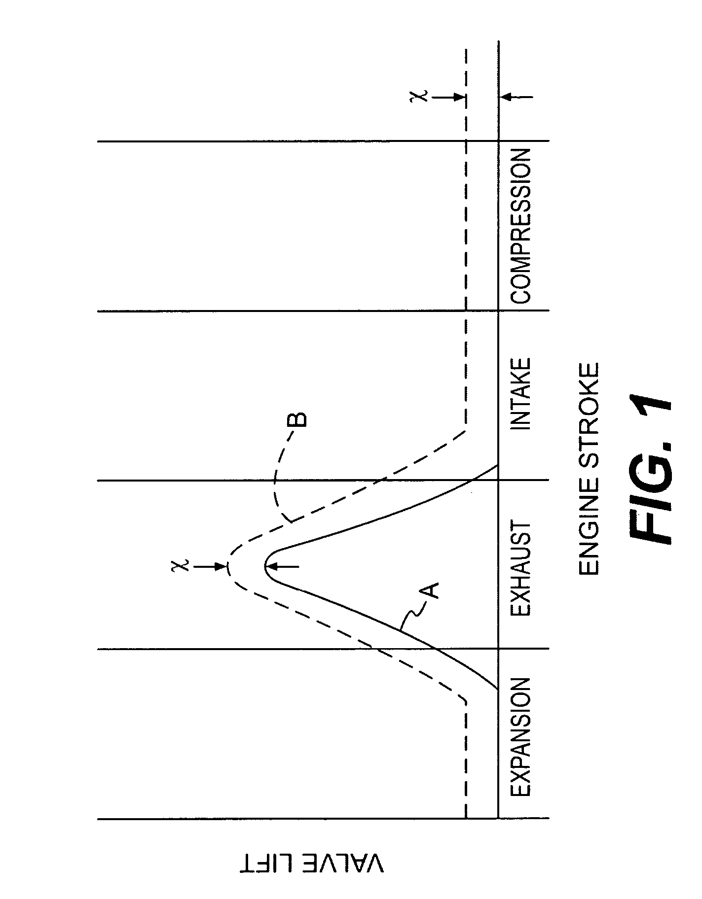
[0021]Applicants have also developed an innovative apparatus for actuating at least one exhaust valve in an internal combustion engine cylinder to produce a main exhaust event during positive power operation and an engine braking effect during engine braking operation, said apparatus comprising: means for opening the at least one exhaust valve for the main exhaust event during an engine exhaust stroke; and means for maintaining the at least one exhaust valve open with a substantially constant lift during engine intake, compression, expansion, and exhaust strokes.
[0022]Ap

Problems solved by technology

Despite these advantages, however, bleeder type engine brakes have not been widely used because they typically produce less braking power than the compression-release type brakes.
One factor that detracts from the braking power of bleeder brakes is their inability to carry out bleeder braking throughout the entire engine cycle.
Previous bleeder brakes have not held the exhaust valve open throughout the engine cycle at a relatively constant lift.
This exaggerated lift can affect bleeder braking power negatively.
The risk of valve to piston contact may require that pockets be drilled into the piston to accommodate the exhaust valve.
Such pockets can have negative effects on positive power and emissions.
Thus, the present Applicants have determined that the inclusion of the main exhaust event in a bleeder braking cycle may reduce the effectiveness of the bleeder brake and / or reduce the desirability of an engine equipped to provide bleeder braking.

Method used


Image

  • Engine braking methods and apparatus
  • Engine braking methods and apparatus
  • Engine braking methods and apparatus

Examples


Embodiment Construction

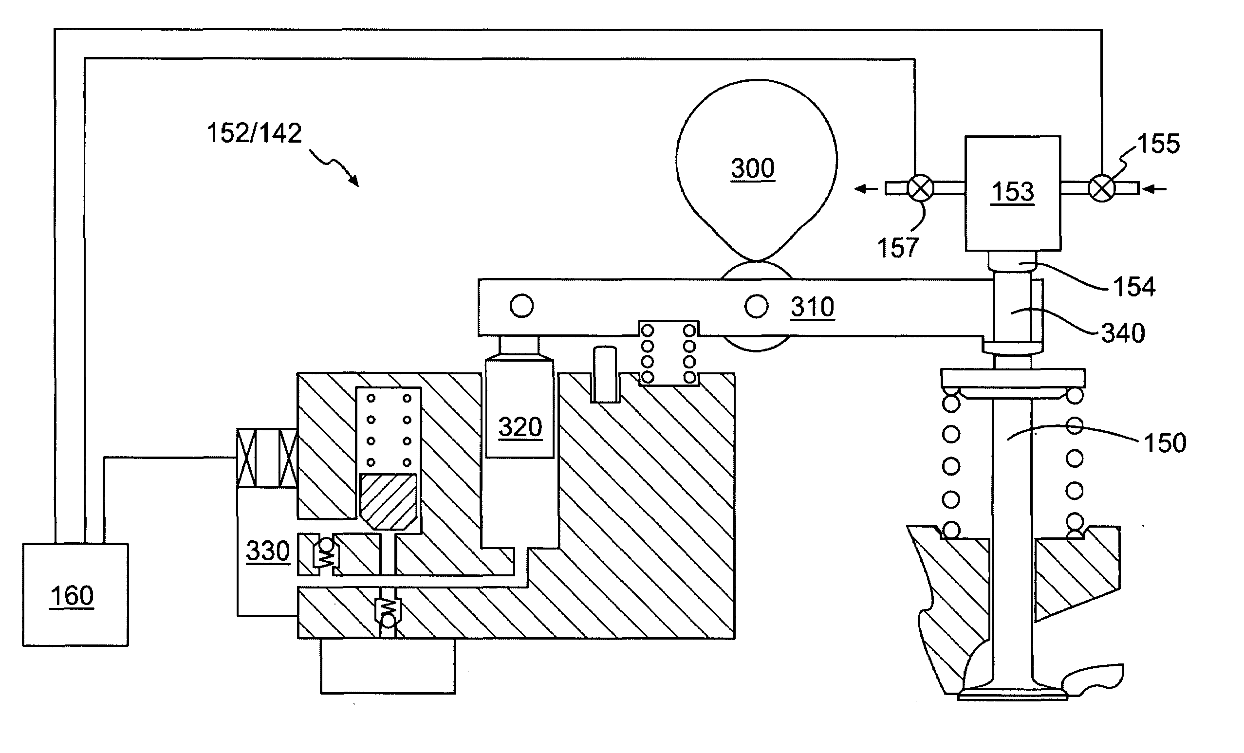
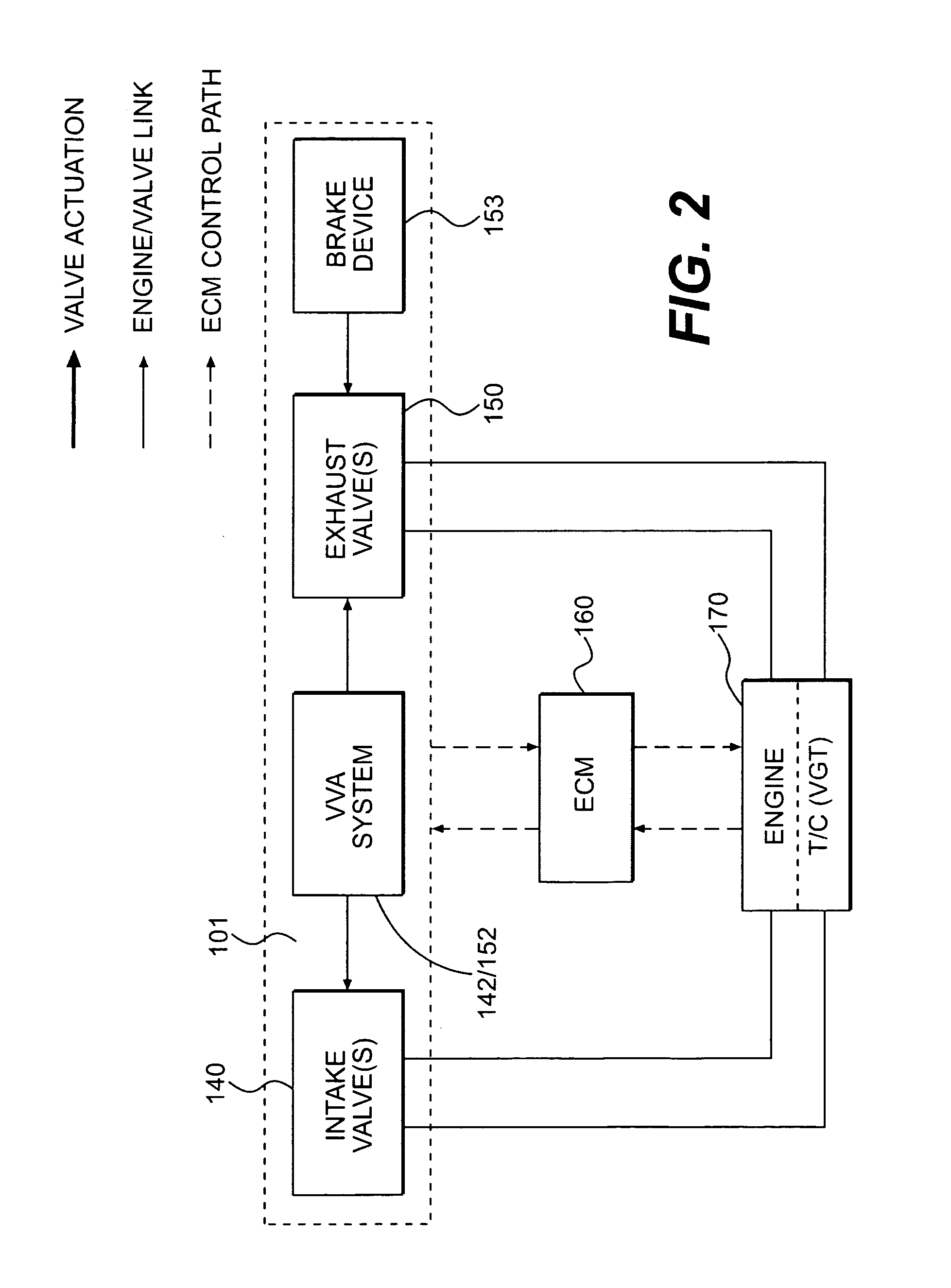
[0038]Reference will now be made in detail to a first system embodiment of the present invention, an example of which is illustrated in FIG. 2. The valve actuation system 101 may include a VVA system 152 / 142 operatively connected to one or more intake valves 140 and one or more exhaust valves 150. The VVA system may include separate components 142 and 152 dedicated to operation of the intake valves and exhaust valves, respectively, or it may be a combined system. An engine braking device 153 also may be operatively connected to the exhaust valves 150. In some embodiments of the present invention, particularly the compression-release embodiments, a discrete engine braking device 153 may be eliminated by incorporating the engine braking functionality into the VVA system 152 / 142.

[0039]The valve actuation system 101, and particularly the VVA system 152 / 142 and the engine braking device 153 may be operatively connected to an ECM 160. The ECM 160 may provide control signals to, and receiv...


PUM


Abstract

Methods and apparatus for providing bleeder-type and compression-release engine braking in an internal combustion engine are disclosed. For bleeder-type engine braking, the exhaust valve is maintained at a small and relatively constant lift throughout all or much of the engine cycle. The engine braking may be combined with exhaust gas recirculation, variable exhaust brake, and / or operation of a variable geometry turbocharger.

Description

FIELD OF THE INVENTION [0001]The present application relates to, and is entitled to the earlier filing date and priority of U.S. provisional patent application No. 60 / 435,295 which was filed Dec. 23, 2002 and entitled “Engine Braking Methods and Apparatus.”Field of the Invention [0002]The present invention relates to methods and apparatus for braking an internal combustion engine. More specifically, the present invention relates to engine braking by controlling the flow of exhaust gas through the engine.BACKGROUND OF THE INVENTION [0003]Engine braking systems have been known for many years. Such systems may be particularly useful in heavy vehicles, such as trucks and buses, because these vehicles have heightened braking needs and commonly use diesel engines. Engine braking systems are needed in diesel engine vehicles because of the inherent cylinder aspiration that results from the valve timings (main intake and main exhaust events) that are required for positive power operation.[00...

Claims


Application Information

Patent Timeline
IPC IPC(8): F02D13/04F01L1/34F01L1/08F01L1/18F01L1/26F01L9/10F01L9/11F01L9/20F01L13/06F02B3/06F02D9/06F02D13/02F02D23/00F02M25/07
CPCF01L1/08F01L1/267F01L1/34F01L9/02F01L9/021F01L13/06F01L13/065F02D9/06F02D13/0207F02D13/0246F02D13/04F02M25/0752F01L1/181Y02T10/121F01L9/04F01L2001/34446F01L2105/00F01L2760/004F01L2800/00F02B3/06F02D13/0273F02D23/00F02M25/0715F02M26/13F02M26/01F01L2305/00F01L9/11F01L9/10F01L9/20
Inventor YANG, ZHOU
Owner JACOBS VEHICLE SYST
Learn More