Container

a container and container technology, applied in the field of containers, can solve the problems of insufficient strength of materials to be comparable, and the difficulty of handling heavy materials, and achieve the effect of outweighing the strength benefits of materials and the inability to meet the requirements of large-scale production

Inactive Publication Date: 2007-01-16
SECURITY PAKS INT
View PDF13 Cites 32 Cited by
  • Summary
  • Abstract
  • Description
  • Claims
  • Application Information

AI Technical Summary

Benefits of technology

[0011]In a second embodiment of the sidewall, double wall construction is utilized. As with the first embodiment, a sidewall includes an inner wall with vertically extending flutes and at least one reinforcing rod. In addition, an outer wall is also added. The outer wall is typically also made of a corrugated plastic material, but the flutes are preferably oriented to extend transversely to those of the inner wall, that is horizontally rather than vertically. Moreover, one or more reinforcing rods may also be inserted into the horizontal flutes for added strength. As with the vertical rods, only selected ones of the flutes receive a rod so that the desirable characteristic of a lightweight wall structure is attained with the added benefits of reinforcement for greater strength.
[0012]The double walled sidewall may also include a dropdown type door. A panel along one of the walls may be removable to provide access. The double wall allows for overlapping between portions of the door and the rest of the sidewall structure for added strength and alignment. A connection is made by one of several well known devices, including hook and loop type fasteners.

Problems solved by technology

Such containers tend to be made of thick, heavy materials that detract from their utility due to difficulty in handling the containers even when empty.
However, such materials may not have sufficient strength to be comparable to very heavy, dense materials as a sidewall in a container.
Moreover, although such materials may have improved strength, the strength benefits may be outweighed by the difficulties of handling heavy material.

Method used


Image

  • Container
  • Container
  • Container

Examples


Embodiment Construction

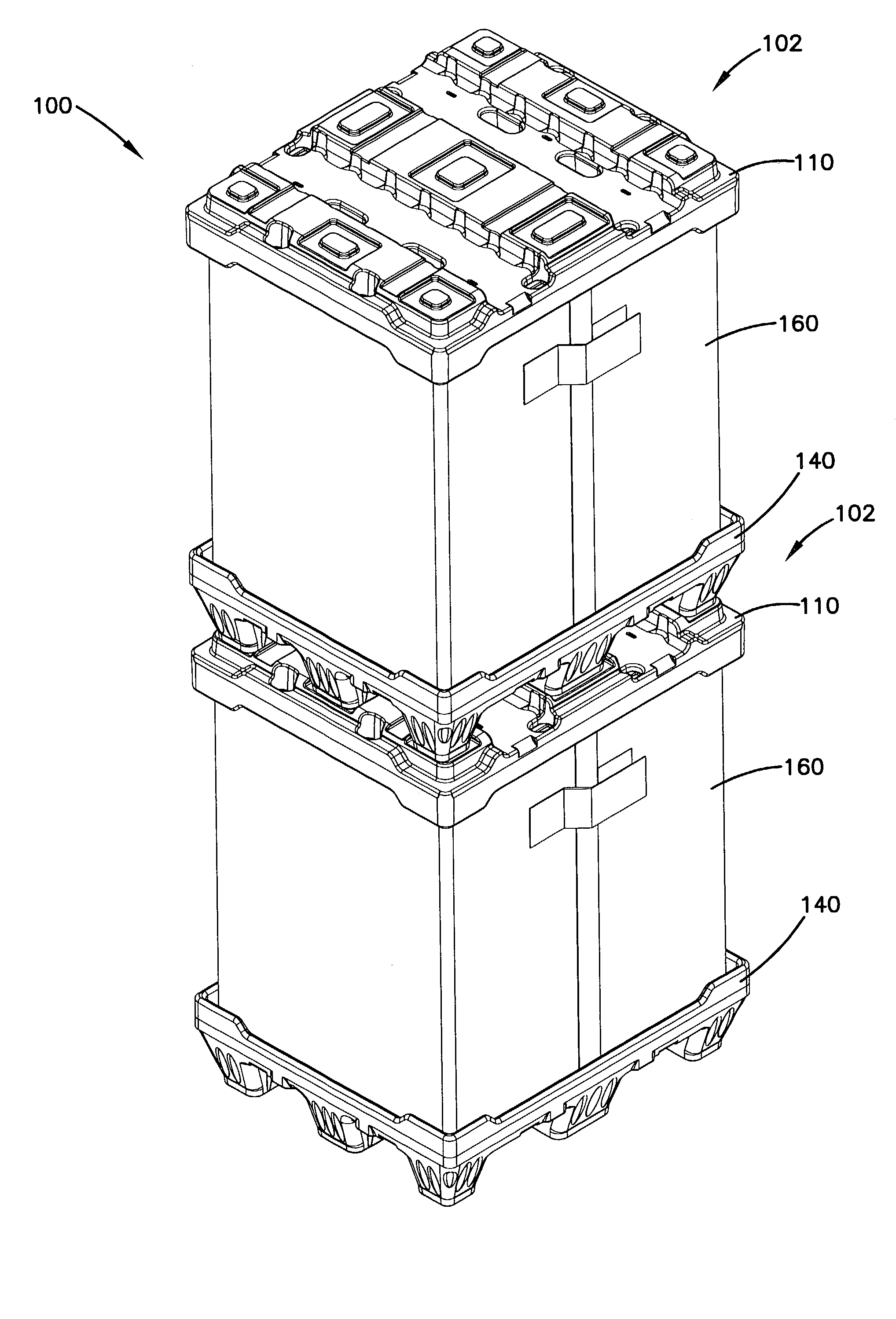
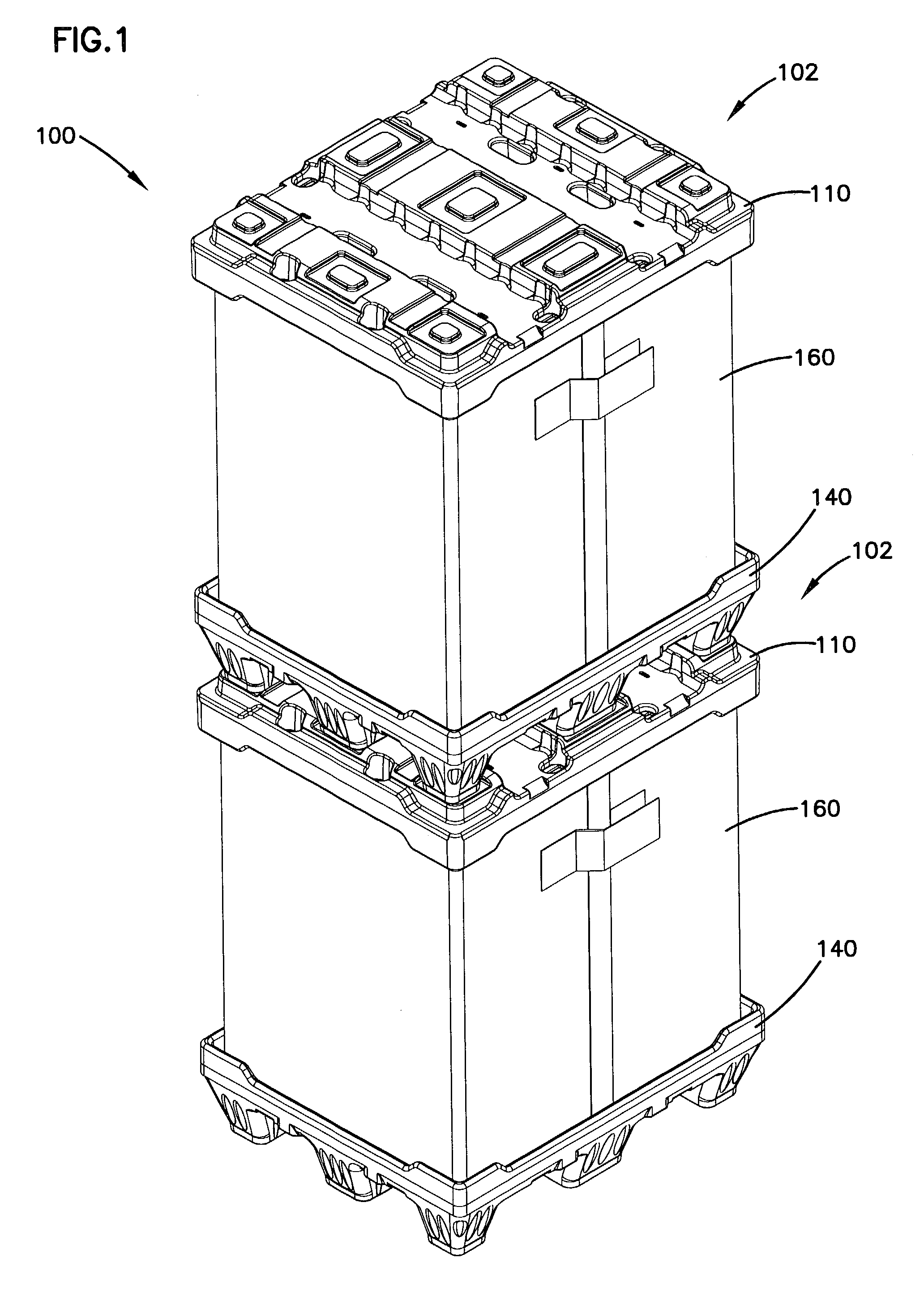
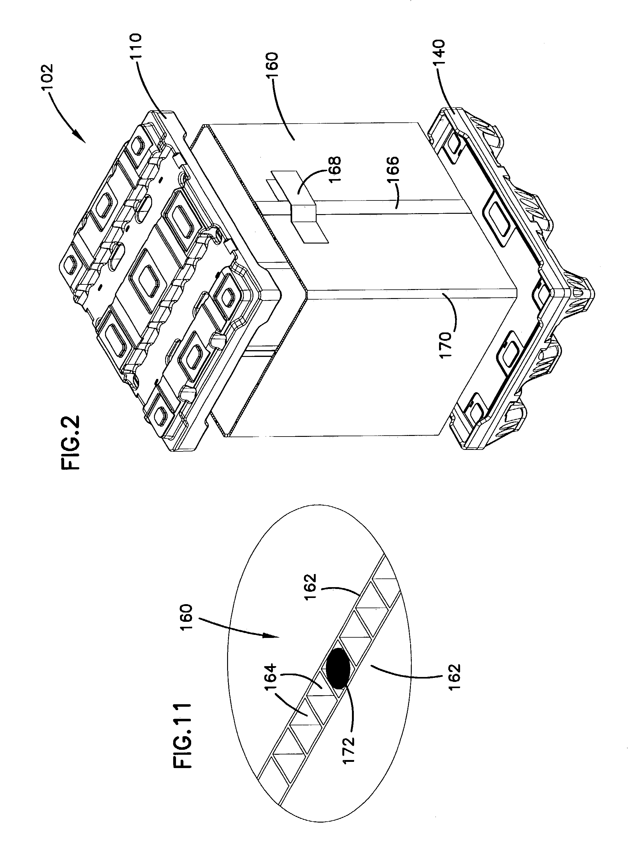
[0034]Referring now to the drawings, wherein like reference numerals and letters indicate corresponding structure throughout the several views, there is shown a container system, generally designated 100. As shown in FIG. 1, the container system 100 includes a first embodiment shown in FIG. 1 and generally designated 102, and a second embodiment of the container system, generally designated 104, shown in FIG. 12. Each of the containers 102 and 104 include interchangeable covers 110 and interchangeable pallet bases 140. The first embodiment 102 also includes a sidewall 160 while the second embodiment 104 has a sidewall 180, shown respectively in FIGS. 2 and 13. As explained hereinafter, the sidewall portions 160 and 180 are interchangeable and may be utilized with the same cover 110 and pallet 140. Moreover, the containers 102 and 104 are both stackable with the other embodiment as well.

[0035]Referring now to FIGS. 3 and 4, the cover 110 includes a planar deck portion 112 configured ...


PUM


Abstract

A container system includes interchangeable components to form an enclosed container. A base in the form of a pallet, a sidewall and a cover are assembled to form an enclosed container. The containers include nesting portions on the pallet and cover so that containers may be stacked when assembled and the components may also be stacked when in storage and nest to resist lateral sliding. The sidewalls include a first embodiment with single wall construction and a second embodiment with double wall construction. The walls are a corrugated plastic construction and include spaced apart reinforcing rods extending into the flutes. The double wall sidewall includes an inner wall with vertically extending flutes having reinforcing rods inserted into spaced apart ones of the flutes while the outer wall has horizontally extending flutes with one or more reinforcing rods inserted therein to provide added strength. The two versions of the sidewall are interchangeable and nest into receiving channels formed in the cover and the pallet.

Description

BACKGROUND OF THE INVENTION[0001]1. Field of the Invention[0002]The present invention relates to a container system, in particular to a lightweight, stackable, high strength container system.[0003]2. Description of the Prior Art[0004]Containers for shipping dense, heavy materials are well known. In order to accommodate and adequately retain and support the materials, the walls of the container must be sufficiently strong. Such containers tend to be made of thick, heavy materials that detract from their utility due to difficulty in handling the containers even when empty. Moreover, it is advantageous to have containers that may be broken down and separated into a cover, base and sidewall elements. The utility of containers further improves if such elements may be stacked when not in use. Such containers further require access by a forklift or pallet jack tines to be useful.[0005]Efforts to achieve lightweight, high strength shipping containers such as are used for shipping paper or o...

Claims


Application Information

Patent Timeline
Patent Type & Authority Patents(United States)
IPC IPC(8): B65D6/10B65D6/16
CPCB65D19/18Y10S229/939B65D2519/00034B65D2519/00069B65D2519/00174B65D2519/00208B65D2519/00268B65D2519/00288B65D2519/00318B65D2519/00338B65D2519/00402B65D2519/00407B65D2519/00422B65D2519/00452B65D2519/00497B65D2519/00502B65D2519/00527B65D2519/00621B65D2519/00641B65D2519/00711B65D2519/00805B65D2519/0096B65D2519/00975B65D2519/00995B65D2313/02
Inventor ELDER, ANDREW W.SKINNER, WILLIAM J.
Owner SECURITY PAKS INT
Why Eureka
Try Eureka