
Electrode plate for secondary battery, method of manufacturing the same, and secondary battery using the same

Active Publication Date: 2007-01-16
SANYO ELECTRIC CO LTD
View PDF5 Cites 3 Cited by
  • Summary
  • Abstract
  • Description
  • Claims
  • Application Information

AI Technical Summary

Benefits of technology

[0023]The present invention is intended to address the foregoing problems encountered in the known art, and it is the first object of the present invention to provide an electrode plate for a secondary battery that can diminish the adverse influence caused by the paste material of the insulating sheet in an electrode body manufacturing apparatus and a battery specification.
[0024]The second object of the present invention is to provide a method of manufacturing an electrode plate manufacturing apparatus for a secondary battery by which adhesion of the paste material to the electrode plate at room temperature is inhibited, such that a plurality of electrode plates can be processed at the same time, resulting in increased production efficiency.
[0025]The third object of the present invention is to provide a highly reliable secondary battery in which a satisfactorily high manufacturing yield is achieved and short-circuits are eliminated by using the electrode plate manufactured through the above-mentioned manufacturing method.
[0028]Under this arrangement, the insulating sheet can be securely made to adhere to a part of the electrode plate and thereby establish an inner short circuit such that it does not protrude from the electrode plate in the longitudinal width direction. Therefore, since the insulating sheet does not protrude from the outline of the electrode plate, the paste material of the insulating sheet is prevented from adhering or sticking to the press machine or the like during the manufacturing process. The use of low-temperature thermoplastic paste as paste material can inhibit adhesion of the paste at room temperature, and prevent the paste from adhering to the electrode body manufacturing apparatus.
[0031]Under this method, after the insulating sheets are adhered to the electrode sheet, an electrode body of a predetermined shape is formed and obtained, thus preventing the insulating sheets from coming off the electrode or electrode plate. As mentioned above, the electrode sheet is coated with active materials to produce a plurality of electrode bodies, and these active materials are subjected to predetermined processing to form the active material layers to which the insulating sheets are made to adhere, and then the electrode plates are cut to a predetermined shape. Therefore, a plurality of electrode plates can be processed and formed at the same time, leading to increased productivity. Since the paste material of the insulating sheets are heated and melted to adhere to the electrode sheet, adhesion of the paste effected at room temperature is suppressed, enabling inhibition of adhesion of the paste to the device in the post-process.
[0033]The use of this electrode plate can provide a highly reliable secondary battery with reduced short circuits and improved manufacturing yield.

Problems solved by technology

Moreover, in the process, peeling off of the active material and wearing away of the manufacturing device cause conductive particles on the non-coated parts of the active materials to remain on the positive and negative electrodes.
When the elliptic cylindrical electrode body is pressed to form a flat electrode body, the remaining burs or particles produced cause the adjacent separator to break away, thereby establishing electrical continuity between positive and negative electrodes via these burs, causing a short circuit.
This short circuit generates extraordinary heat during use of the battery, lowering the capacity thereof, thereby shortening its service life.
Further, it is actually difficult if not impossible to fix or secure the insulating tape having the same dimension as the electrode so as not to protrude from the side edges of the electrode.
This often necessitates cumbersome handling, such as cleaning of the press machine or the like, leading to reduced production efficiency.
When an electrode body is inserted in an exterior can, the paste material of the insulating tape often adheres to the can, making it difficult to insert the electrode body further.
This unfortunately results in extremely low efficiency in the production of the electrode body.

Method used


Image

  • Electrode plate for secondary battery, method of manufacturing the same, and secondary battery using the same
  • Electrode plate for secondary battery, method of manufacturing the same, and secondary battery using the same
  • Electrode plate for secondary battery, method of manufacturing the same, and secondary battery using the same

Examples


Embodiment Construction

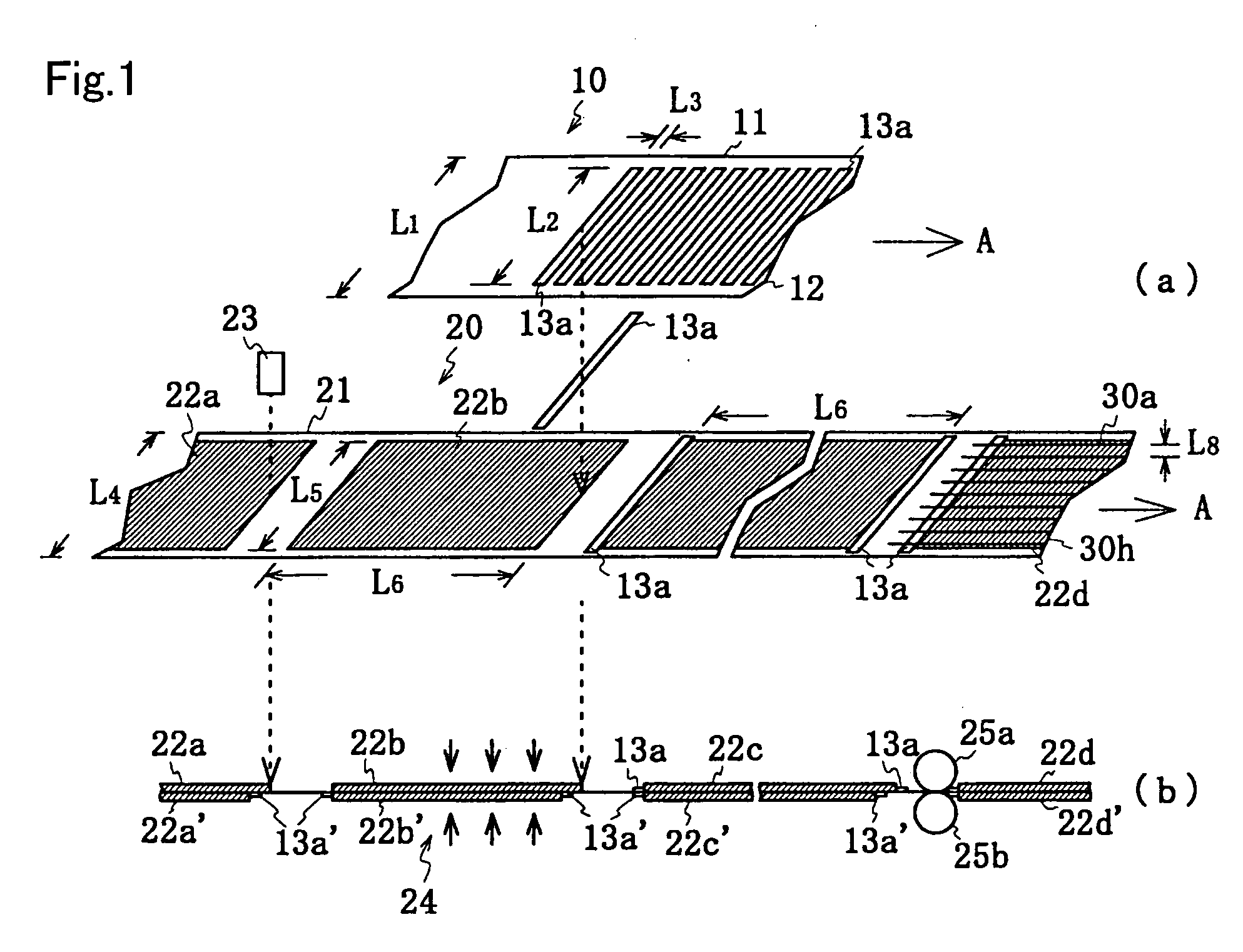
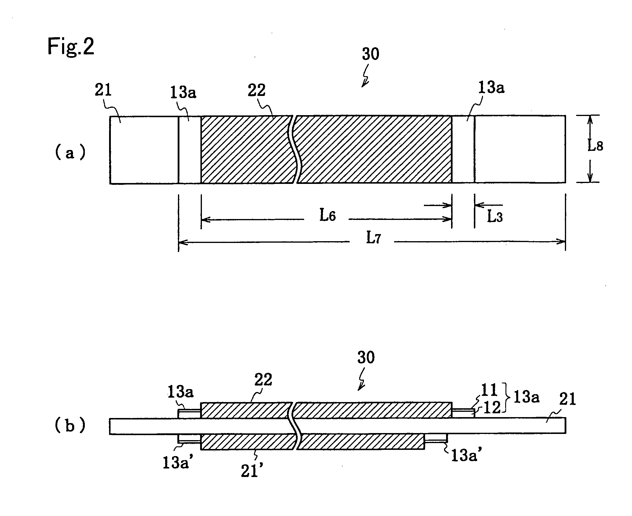
[0039]The electrode plate according to the invention and the method of manufacturing the same is hereafter described with reference to the accompanying drawings. FIG. 1 is a schematic diagram explaining the method of sticking an insulating sheet. FIG. 1(a) is a detailed diagram showing the relationship between the insulating sheet and an electrode sheet as well as the insulating sheet, and FIG. 1(b) is a side view of the electrode sheet. FIG. 2 shows one piece of the electrode plate manufactured by the manufacturing method of FIG. 1. FIG. 2(a) is a detailed plane view thereof, and FIG. 2(b) is a side view thereof.

[0040]An insulating sheet 10 as well as an electrode sheet 20 both having a predetermined shape are prepared in advance. The insulating sheet 10 includes a sheet material 11 having a predetermined width and thickness, and a paste layer 12 attached on the back surface of the sheet material 11. The sheet material 11 is formed by using a sheet of paper or resin material includ...


PUM

PropertyMeasurementUnit
Timeaaaaaaaaaa
Temperatureaaaaaaaaaa
Lengthaaaaaaaaaa

Abstract

An electrode plate for a secondary battery is provided for reducing adverse influences caused by paste of an insulating sheet in an electrode body and a battery specification. Active material layers 22a to 22d and 22a′ to 22d′ are formed on at least one surface of an electrode sheet 20 over a wider range than a predetermined width of an electrode and over a predetermined length. An insulating sheet 13a is made to adhere to a possible short-circuit portion of the electrode sheet 20 which portion is opposed to another electrode. The electrode sheet 20 and an insulating member are simultaneously cut to form an electrode plate having a predetermined shape, wherein the insulating member has a low-temperature thermoplastic paste material applied on one side thereof, and is made to adhere to the electrode sheet 20 through heat adhesion.

Description

BACKGROUND OF THE INVENTION[0001]1. Field of the Invention[0002]The present invention relates to an electrode plate suitable for a nonaqueous electrolyte secondary battery, e.g., a lithium secondary battery or the like, a method of manufacturing the same, and a secondary battery using the same. More specifically, the invention relates to (1) an electrode plate with an insulating jointed to the plate effectively and accurately in a predetermined position to prevent short circuits, (2) a method of manufacturing the same, and the like.[0003]2. Description of the Background Art[0004]Because of the rapid growth and development of portable electronic devices, the specification requirements for a battery used for such products have become more and more exacting. In particular, a compact low-profile battery with a high capacity, excellent cycle character, and stable performance is absolutely desirable. In the field of secondary batteries, lithium secondary batteries have generated more inte...

Claims


Application Information

Patent Timeline
IPC IPC(8): H01M6/00H01M2/16H01M2/34H01M4/13H01M4/139H01M4/72H01M10/04H01M10/05
CPCH01M4/0404H01M10/0431H01M4/1391H01M4/1393Y10T29/49115H01M10/058Y02E60/122Y10T29/10Y10T29/49112H01M10/0525Y02E60/10Y02P70/50B21B39/008B21B2203/18
Inventor YANAGAWA, TOSHIROUFUKUTA, TADATOSHITANAKA, HITOSHIOKUMURA, YOSHINOBUOHSHITA, RYUJIMIYAMOTO, YOSHIKUMIOKAZAKI, JUN
Owner SANYO ELECTRIC CO LTD
Learn More