Method and system for obstacle detection

a technology of obstacle detection and detection method, applied in the direction of counting objects on conveyors, using reradiation, instruments, etc., can solve the problem that the cost of micro-mechanical systems may not be suitable for some applications, and achieve the effect of facilitating rapid and reliable detection of objects and/or estimation

Active Publication Date: 2007-01-16
DEERE & CO
View PDF20 Cites 59 Cited by
  • Summary
  • Abstract
  • Description
  • Claims
  • Application Information

AI Technical Summary

Benefits of technology

[0004]A method and system for obstacle detection facilitates rapid and reliable detection of an object and / or estimation of a distance between the system and the object. A transmitter emits generally linear beams of electromagnetic radiation with a transmitted radiation pattern within a defined spatial zone. A camera collects one or more images of the defined spatial zone. A data processor detects a presence of an object in the collected image based on an observed illumination radiation pattern on an object formed by at least one of the generally linear beams. A distance estimator estimates a distance between the object and the camera based on a material change (e.g., an observed shift in one or more positions) of the generally linear beams from the transmitted radiation pattern to the observed illumination radiation pattern.

Problems solved by technology

Although micro-electromechanical systems may be applied to improve reliability and improve the response time of the scanning lasers, the cost of micro-mechanical systems may not be appropriate for some applications.

Method used


Image

  • Method and system for obstacle detection
  • Method and system for obstacle detection
  • Method and system for obstacle detection

Examples


Embodiment Construction

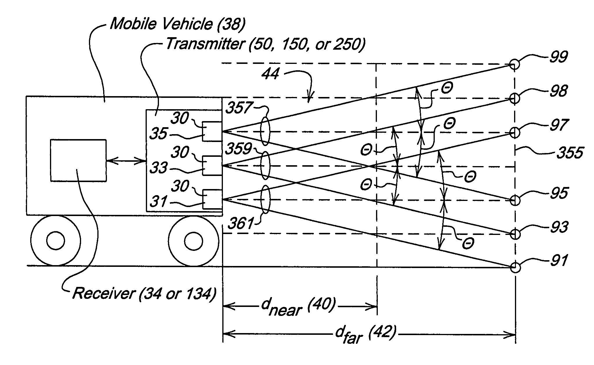
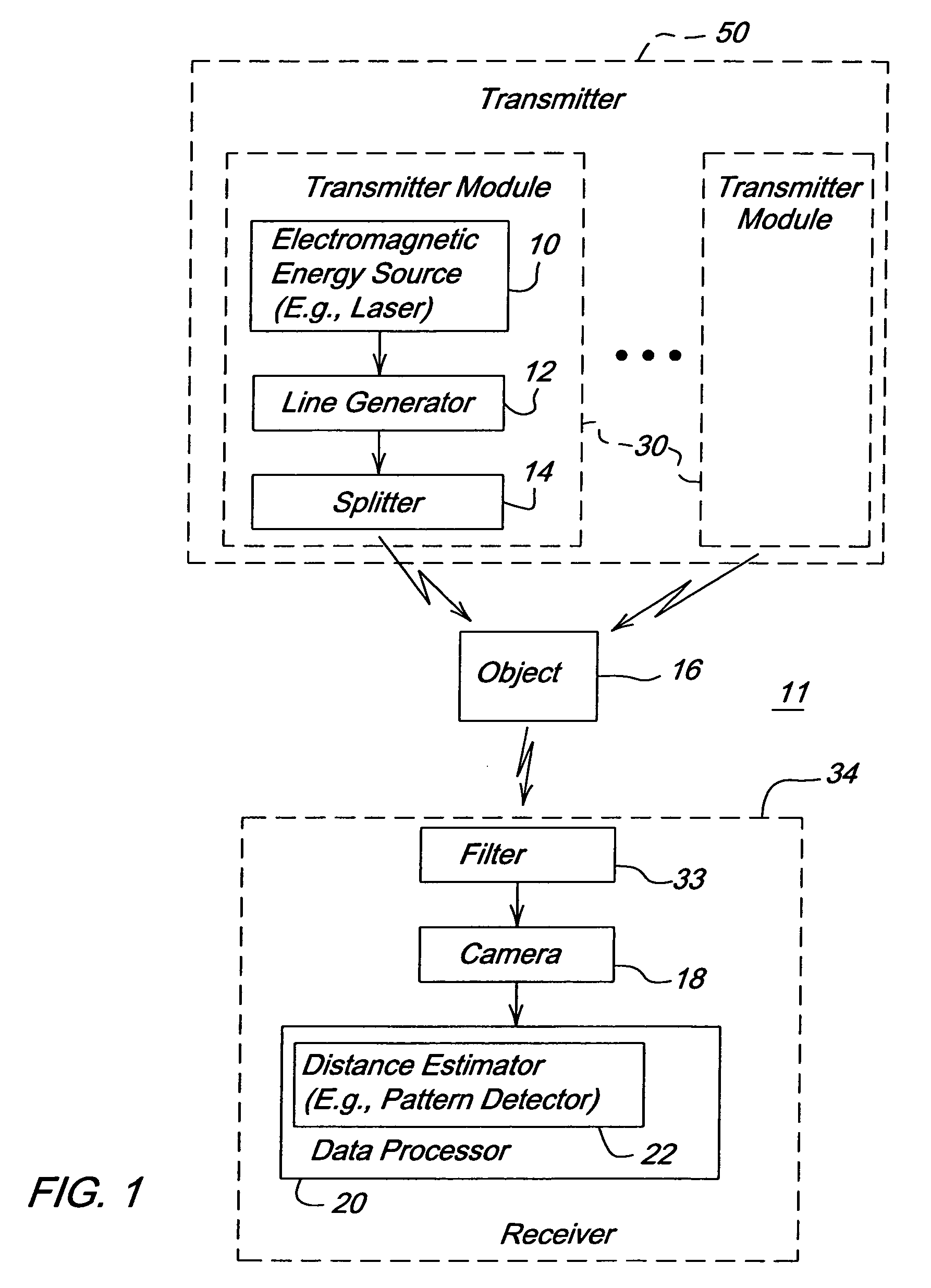
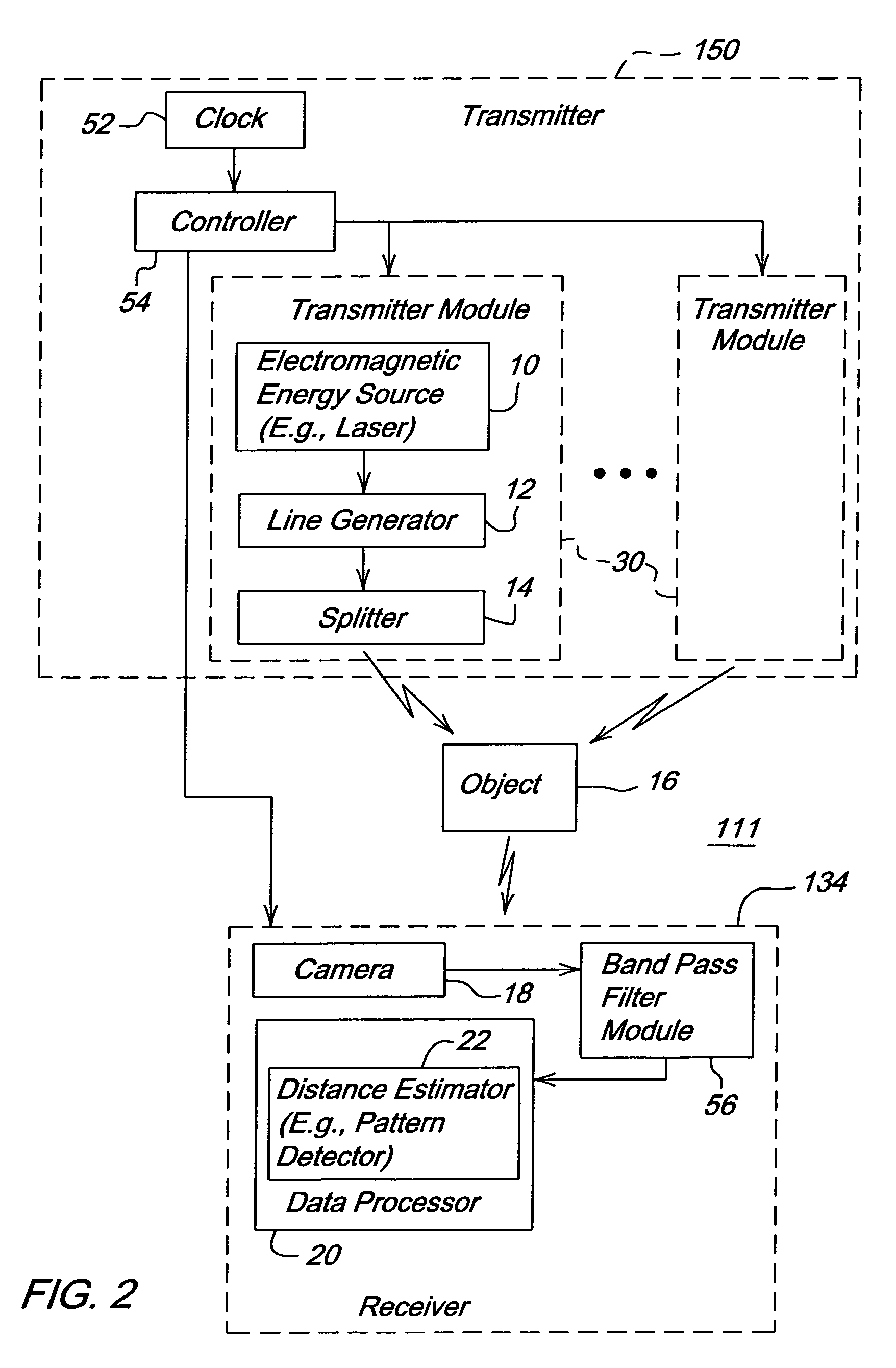
[0020]In accordance with one embodiment of the invention, FIG. 1 is a block diagram of an obstacle detection system 11. One or more objects 16 or obstacles of a given size in a field of regard must be known with sufficient temporal resolution to enable safe passage of a vehicle at a given speed, acceleration, and heading. The obstacle detection system 11 comprises a transmitter 50 and a receiver 34. The transmitter (e.g., 50) and the receiver (e.g., 34) may collectively be referred to as an optical device or optical unit herein. The transmitter 50 further comprises a group of transmitter modules 30 (e.g., a laser line emitters).

[0021]Each transmitter module 30 includes an electromagnetic energy source 10 (e.g., a laser) that provides electromagnetic energy (e.g., light, ultraviolet light or infrared radiation) to a line generator 12. For example, the electromagnetic energy source 10 may provide a generated beam, a columnar beam or another input beam of electromagnetic energy to the ...


PUM


Abstract

A method and system for detecting the presence of an object or the distance between the system and an object supports the provision of rapid and reliable obstacle detection. A transmitter emits generally linear beams of electromagnetic radiation with a transmitted radiation pattern within a defined spatial zone. A camera collects an image of the defined spatial zone. A data processor detects a presence of an object in the collected image based on an observed illumination radiation pattern on an object formed by at least one of the generally linear beams. A distance estimator estimates a distance between the object and the optical device based on a change (e.g., an observed shift in one or more positions of generally linear beams) from the transmitted radiation pattern to the observed illumination radiation pattern.

Description

FIELD OF THE INVENTION[0001]This invention relates to a method and system for obstacle detection for a vehicle.BACKGROUND OF THE INVENTION[0002]In the prior art, scanning lasers may use mechanical components (e.g., a mirror or other movable member) to scan a beam over a field of view. The mechanical components may require the scanning laser to cycle through an entire range of beam orientations, rather than supporting random access to any particular orientation of the scanning beam. For obstacle detection applications of a vehicle, the response time for collecting image data should be rapid over a wide field of view to facilitate early recognition and avoidance of obstacles.[0003]Although micro-electromechanical systems may be applied to improve reliability and improve the response time of the scanning lasers, the cost of micro-mechanical systems may not be appropriate for some applications. Further, because a micro-electromechanical system may generate multiple lines of light from a...

Claims


Application Information

Patent Timeline
Patent Type & Authority Patents(United States)
IPC IPC(8): G06M7/00G01B11/24G01S17/87G01S17/931
CPCG01S17/936G01S17/87G01S17/08G01S11/12G01S17/931
Inventor ANDERSON, NOEL WAYNEPUHALLA, JEFFREY SCOTT
Owner DEERE & CO
Why Eureka
Try Eureka