Stator pole structure for an electrical machine

a technology of electrical machines and pole structures, applied in the direction of dynamo-electric machines, magnetic circuit rotating parts, magnetic circuit shapes/forms/construction, etc., can solve the problems of closing the tips onto the rotor, generating excessive audible noise, and affecting the operation of the whole c cor

Inactive Publication Date: 2007-01-16
ROLLS ROYCE PLC
View PDF15 Cites 37 Cited by
  • Summary
  • Abstract
  • Description
  • Claims
  • Application Information

AI Technical Summary

Benefits of technology

[0006]In accordance with the present invention, there is provided an electrical machine comprising a stator and a rotor, the stator including stator core members spaced relative to one another and at least one stator pole member configured by itself or with other members to straddle two or more stator core members to provide structural stability.

Problems solved by technology

Thus, the tips tend to move in operation and the whole C core is subject to vibration and can generate excessive audible noise.
Also, even when stationary, the C cores as a whole experience the closing force which over time causes creepage of the bonding adhesive leading to closure of the tips onto the rotor even if vibration induced delamination has not occurred.

Method used


Image

  • Stator pole structure for an electrical machine
  • Stator pole structure for an electrical machine
  • Stator pole structure for an electrical machine

Examples


Embodiment Construction

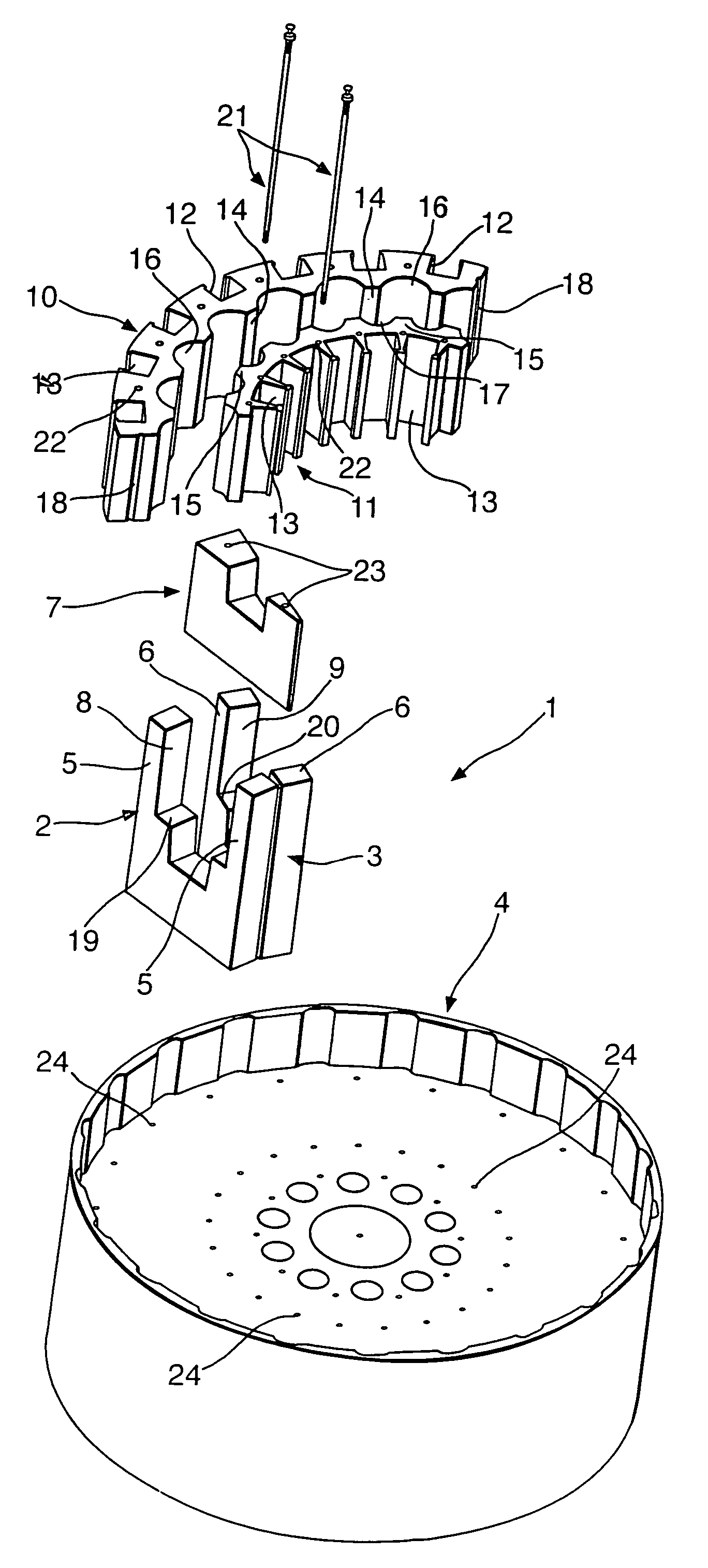
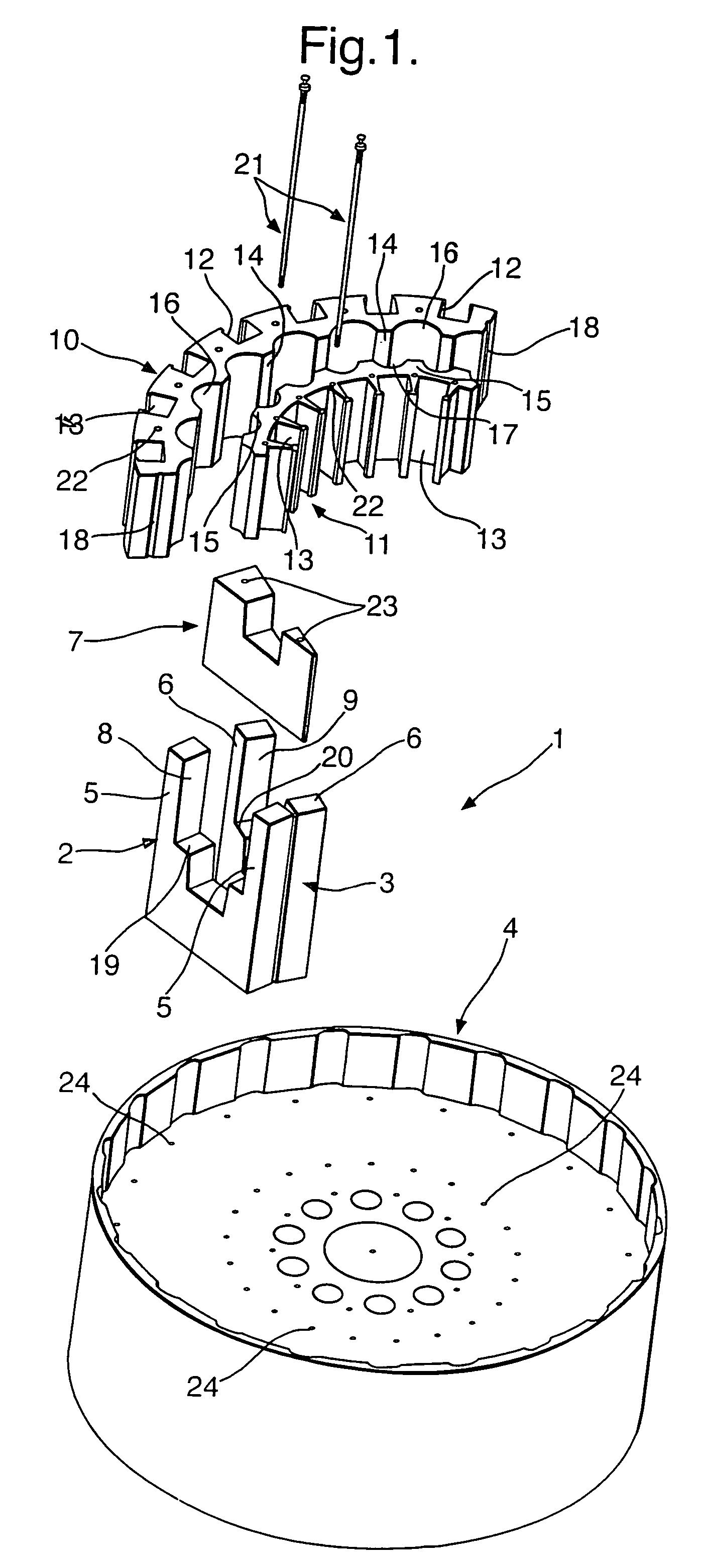
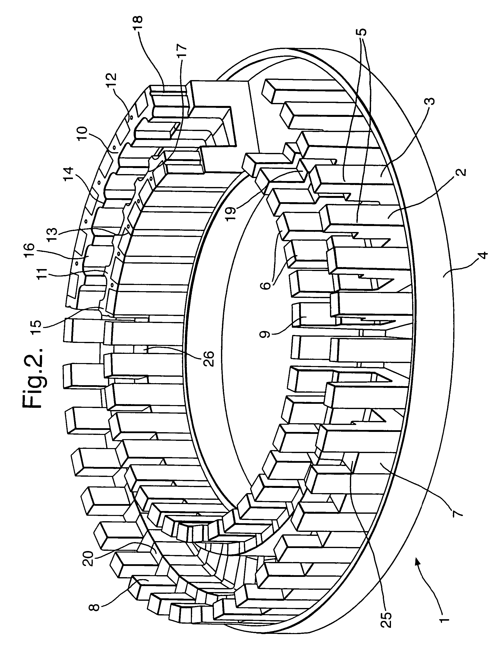
[0027]A motor operating upon transverse flux principles consists of a stator winding in the form of a circular coil co-axial with a rotor. The stator links the magnetic flux generated by permanent magnets mounted on the rim of a rotor disc through a series of stator cores. These stator cores are spaced about the rotor path. The stator cores are typically laminated assemblies of grain orientated material shaped in order to provide the desired stator core to rotor magnetic interaction. Normally, a rotor rim and co-operating stator core and stator coil assembly are located on either side of the rotor disc in order to provide greater torque potential. Additionally, more concentric rims may be located on each side of the rotor disc at different diameters, each with its own co-operating ring of stator cores and stator coil for greater torque potential.

[0028]In order to achieve high electrical machine power density it is desired to maximise magnetic flux interaction. In such circumstances,...


PUM


Abstract

An electrical machine, such as a transverse flux motor, incorporates a stator core assembly 1. The stator core assembly 1 comprises a stator frame 4 upon which stator cores 2,3 are located with spacer elements 7 therebetween. A number of stator pole members 10,11 are located such that channels 13 in these members 10,11 accommodate limbs 5,6 of the cores 2,3. The stator pole members 10,11 straddle more than two limbs 5,6 in order to provide greater structural stability for the assembly 1 despite magnetic flux cycling and other distortion effects. By such greater structural stability more accurate control of a gap between the stator core assembly 1 and a rotor in the machine can be maintained.

Description

[0001]This application is a continuation of PCT / GB2003 / 005010 filed Nov. 17, 2003, the priority of which is claimed.FIELD OF THE INVENTION[0002]The present invention relates to an electrical machine and more particularly to a transverse flux motor including a stator assembly and a rotor.BACKGROUND OF THE INVENTION[0003]It is known to provide electrical machines which comprise a stator assembly formed from laminations of appropriate material in order to create poles which magnetically interengage with a rotor. The electrical machine constitutes a motor driven by magnetic engagement between the stator assembly and the rotor. Typically, the stator is appropriately constructed in order to comprise a succession of electromagnets whose pole characteristics can be alternated in order to drive the rotor, which in this case incorporates permanent magnets.[0004]The stator assembly typically comprises a number of C shaped stator cores assembled in a circular hub with the rotor passing through ...

Claims


Application Information

Patent Timeline
Patent Type & Authority Patents(United States)
IPC IPC(8): H02K1/22H02K1/00H02K1/14H02K1/18H02K15/02H02K15/12
CPCH02K1/145H02K1/182H02K15/12H02K15/022H02K2201/12
Inventor GILMOUR, KENNETH SMYERS, TIMOTHY M S
Owner ROLLS ROYCE PLC
Why Eureka
Try Eureka