Vehicular lamp
- Summary
- Abstract
- Description
- Claims
- Application Information
AI Technical Summary
Benefits of technology
Problems solved by technology
Method used
Image

Examples
first embodiment
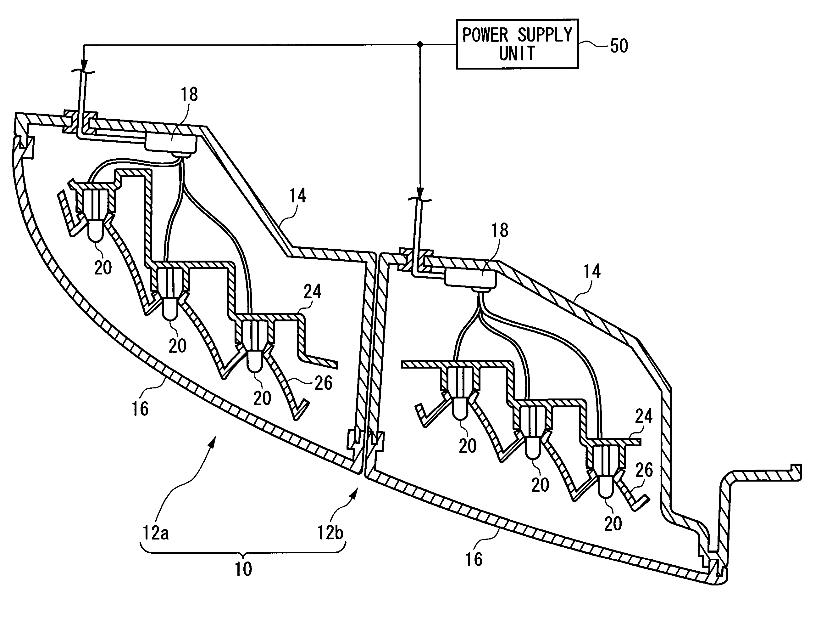
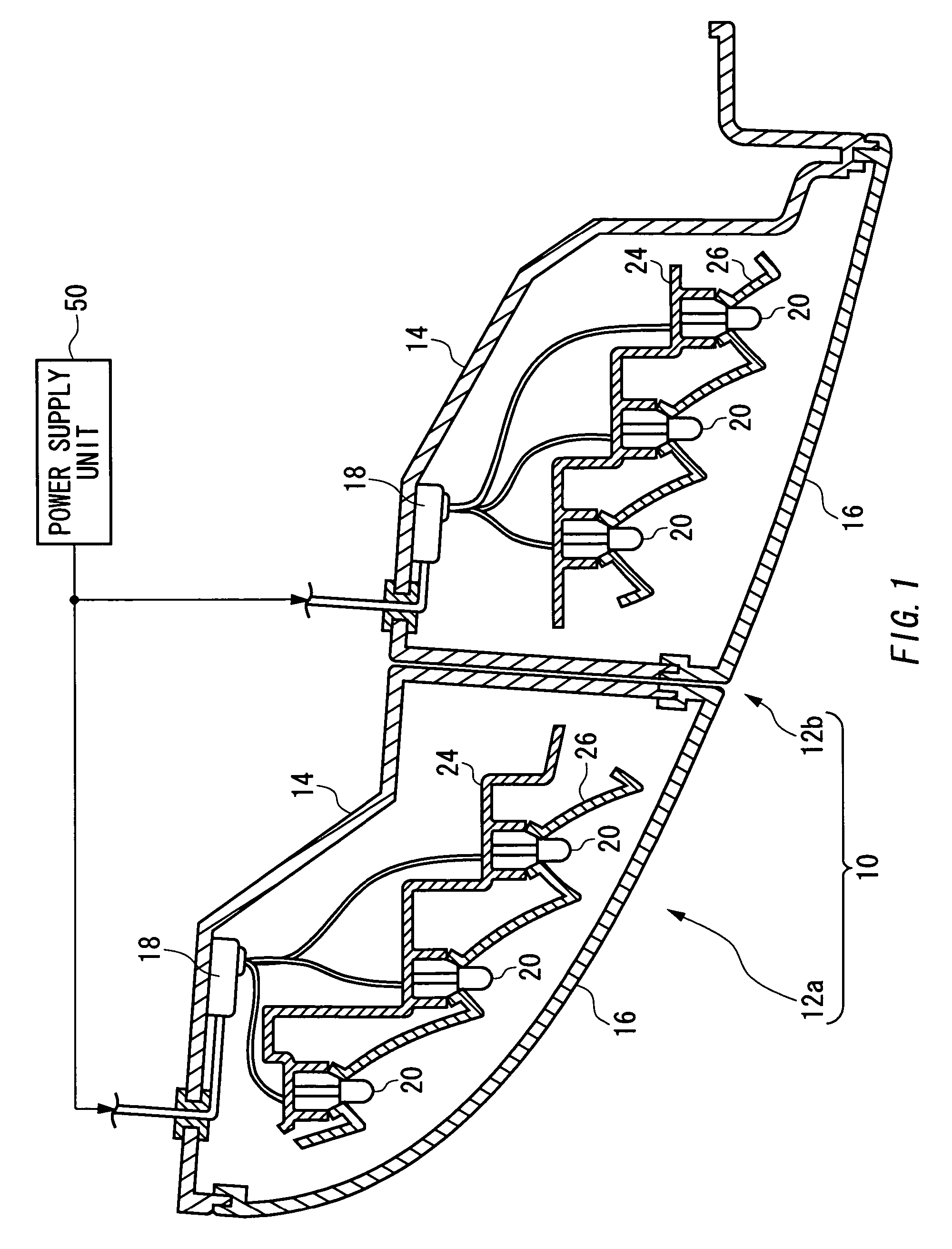
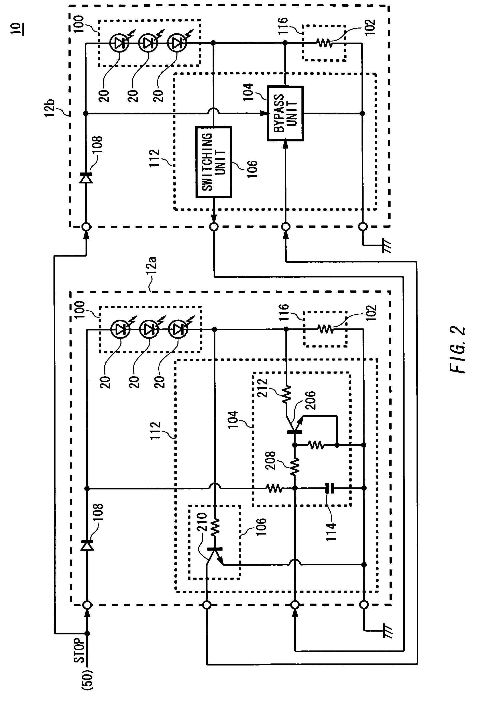
[0042]FIG. 2 is a circuit diagram illustrating a part of a circuit configuration of the vehicular lamp 10 according to the present invention. In the present embodiment, the vehicular lamp 10 includes a plurality of marker lamps 12a and 12b which act as a stop lamp. The marker lamp 12a has the same or similar configuration as / to the marker lamp 12b, each of which includes a light source unit 100, a diode 108, a current limiting unit 116, and an electric current control unit 112.
[0043]The light source unit 100 includes a plurality of light emitting diodes 20 connected in series. The plurality of light emitting diodes 20 emit light according to electric current supplied from the power supply unit 50 through diode 108 so that the marker lamp 12 operates properly. Alternatively, the light source unit 100 includes single light emitting diode 20, or includes a plurality of light emitting diodes 20 connected in parallel.
[0044]In addition, in the present embodiment, the light source units 10...
second embodiment
[0058]FIG. 3 is a circuit diagram illustrating a part of a circuit configuration of the vehicular lamp 10 according to the present invention. In the present embodiment, the marker lamp 12a includes a diode 108, a light source unit 100, a plurality of current limiting units 116a and 116b and a plurality of current control units 112a and 112b. The marker lamp 12b includes a light source unit 100. Since like reference numbers are used to denote like parts in FIG. 2 and FIG. 3, the explanation of those parts will be omitted to avoid redundancy except otherwise described below.
[0059]In the present embodiment, the current control unit 112a and the current limiting unit 116a correspond to the light source unit 100 in the marker lamp 12a, and the current control unit 112b and the current limiting unit 116b corresponds to the light source unit 100 in the marker lamp 12b. Functions of the current control unit 112a and the current limiting unit 116a are the same or similar as / to those of the c...
third embodiment
[0061]FIG. 4 is a circuit diagram illustrating a part of a circuit configuration of the vehicular lamp 10 according to the present invention. In the present embodiment, the function and configuration of the marker lamp 12a is the same or similar as / to those of the marker lamps 12b, and the plurality of the marker lamps 12a and 12b act as at least one of a stop lamp and a tail lamp and are operated depending on an instruction from outside. Since like reference numbers are used to denote like parts in FIG. 2 and FIG. 4, the explanation of those parts will be omitted to avoid redundancy except otherwise described below.
[0062]Each of the marker lamps 12a and 12b includes a light source unit 100, a plurality of diodes 108a and 108b, a current limiting unit 116, and a current control unit 112. When the vehicular lamp 10 acts as a tail lamp, each of the marker lamps 12a and 12b receives positive voltage from the power supply unit 50 provided in the exterior of the marker lamps 12a and 12b ...
PUM
 Abstract
Description
Claims
Application Information
 - Generate Ideas
- Intellectual Property
- Life Sciences
- Materials
- Tech Scout
- Unparalleled Data Quality
- Higher Quality Content
- 60% Fewer Hallucinations
Browse by: Latest US Patents, China's latest patents, Technical Efficacy Thesaurus, Application Domain, Technology Topic, Popular Technical Reports.
© 2025 PatSnap. All rights reserved.Legal|Privacy policy|Modern Slavery Act Transparency Statement|Sitemap|About US| Contact US: help@patsnap.com