Modular heatsink, electromagnetic device incorporating a modular heatsink and method of cooling an electromagnetic device using a modular heatsink

a heatsink and electromagnetic device technology, applied in the direction of transformer/inductance cooling, electrical apparatus construction details, lighting and heating apparatuses, etc., can solve the problems of poor thermal conductivity, no heat flow path is particularly efficient, and heat dissipation becomes increasingly importan

Inactive Publication Date: 2007-01-16
HONEYWELL INT INC
View PDF25 Cites 49 Cited by
  • Summary
  • Abstract
  • Description
  • Claims
  • Application Information

AI Technical Summary

Problems solved by technology

However, because the windings are often tightly wound and may be coated with an insulating material, heat generated internally must either transfer across several layers of insulation, travel through the core material (which may exhibit poor thermal conductivity) or along the winding conductive path and into the wiring or bussing connected to the device.
None of these heat flow paths are particularly efficient.
Heat dissipation becomes increasingly important when electromagnetic devices operate at high power levels.
High temperatures generated by these devices limit the power levels at which they can operate.
Such temperature limits thus may also adversely affect the volumetric and weight performance of equipment incorporating the electromagnetic devices.
Heatsinks are known for cooling electronic equipment, but are generally only useful for removing heat from exposed surfaces of a device.

Method used


Image

  • Modular heatsink, electromagnetic device incorporating a modular heatsink and method of cooling an electromagnetic device using a modular heatsink
  • Modular heatsink, electromagnetic device incorporating a modular heatsink and method of cooling an electromagnetic device using a modular heatsink
  • Modular heatsink, electromagnetic device incorporating a modular heatsink and method of cooling an electromagnetic device using a modular heatsink

Examples


Embodiment Construction

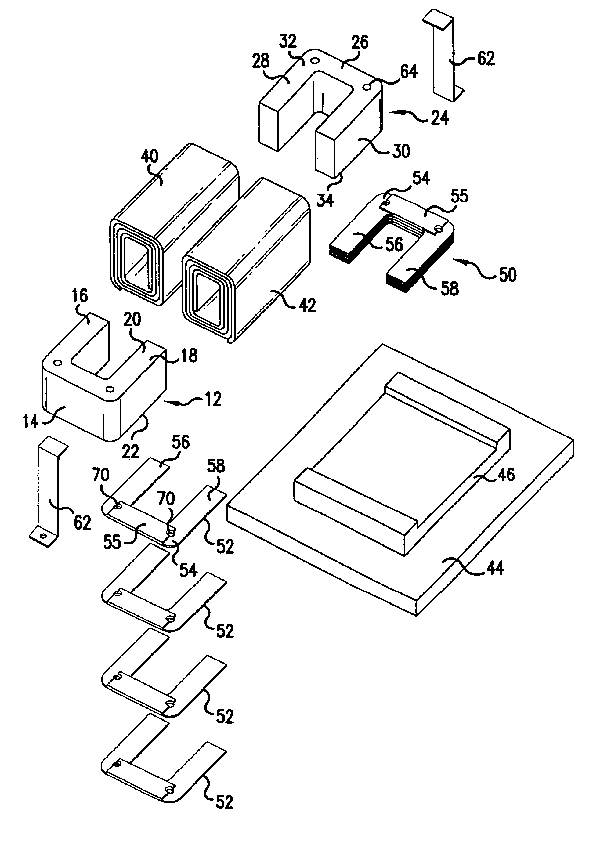
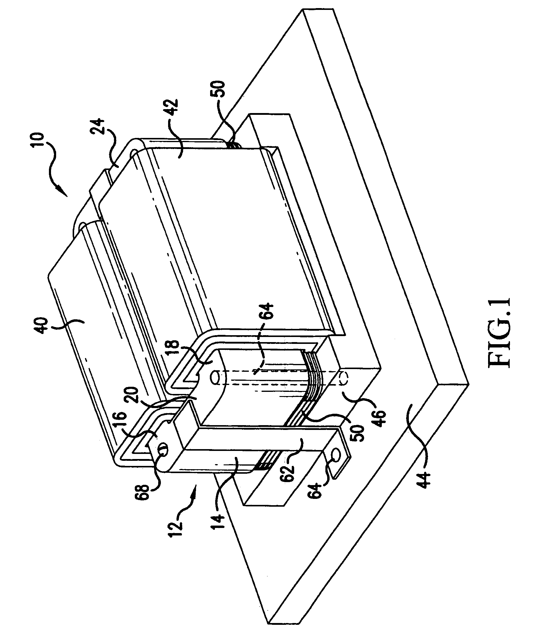
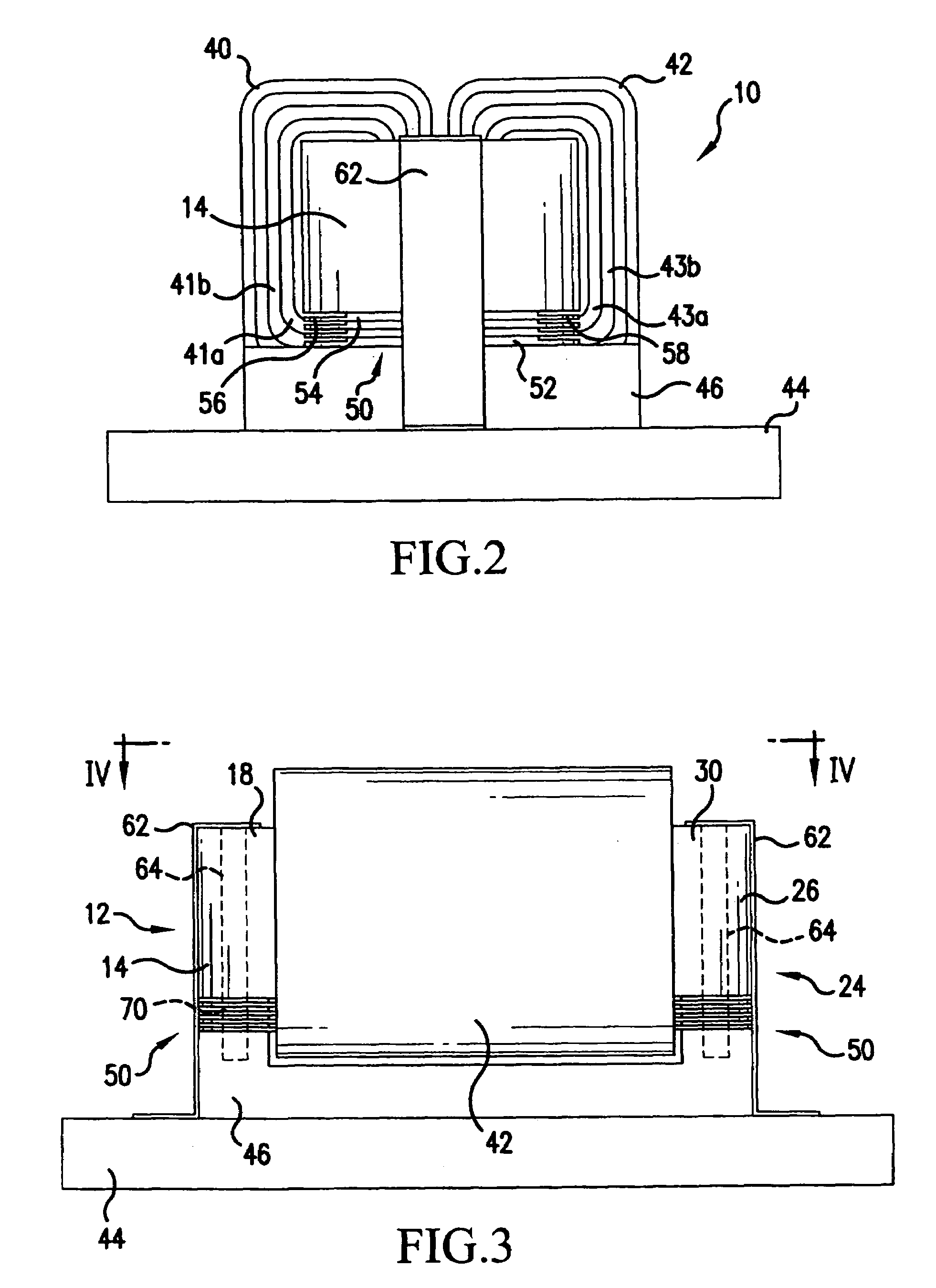
[0018]Referring now to the drawings, wherein the showings are for the purpose of illustrating embodiments of the invention only and not for the purpose of limiting same, FIGS. 1, 5 and 6 show an electromagnetic device 10, which may be, for example, a transformer or inductor, comprising a first core element 12 having a body portion 14 and a first arm 16 and second arm 18 extending therefrom, the first core element 12 including a top 20 and bottom 22 (“top” and “bottom” being used with reference to the orientation of device 10 in FIG. 1). Electromagnetic device 10 further includes a second core element 24 having a body portion 26 and a first arm 28 and second arm 30 extending therefrom, the second core element 24 including a top 32 and bottom 34. First and second core elements 12, 24 are illustrated as being separated by a gap but could alternately be in contact with one another or comprise opposite ends of a single core element depending on the nature of the electromagnetic device 10...


PUM

PropertyMeasurementUnit
thicknessaaaaaaaaaa
heat conductingaaaaaaaaaa
lengthaaaaaaaaaa

Abstract

An electromagnetic device (10) includes a core (12) having first and second arms (16, 18) connected by at least one body (14), a first winding (40) having multiple turns (41a, 41b) on the first arm (16) and a second winding (42) having multiple turns (43a, 43b) on the second arm (18), and a heatsink (50) having a first plurality of U-shaped heatsink elements (52) each including first and second legs (56, 58) aligned with the first and second arms (16, 18) and having a first thickness connected by a base (54) having a second thickness greater than the first thickness, the base (54) of each of the plurality of elements (52) being in contact with the base (54) of an adjacent heatsink element (52).

Description

FIELD OF THE INVENTION[0001]The present invention is directed to a modular heatsink, an electromagnetic device incorporating a modular heatsink and a method of cooling an electromagnetic device using a modular heatsink, and, more specifically, to a heatsink comprising a plurality of generally U-shaped heatsink elements adapted to extend between the core and windings or between adjacent winding turns of an electromagnetic device, an electromagnetic device incorporating these heatsink elements, and a method of cooling an electromagnetic device using such heatsink elements.BACKGROUND OF THE INVENTION[0002]Many electromagnetic devices generate heat during use and require cooling to prevent the temperature of the device and / or surrounding environment from becoming too high. Certain devices, including transformers and inductors, include current carrying windings, and heat generated in these windings must be dissipated. However, because the windings are often tightly wound and may be coate...

Claims


Application Information

Patent Timeline
Patent Type & Authority Patents(United States)
IPC IPC(8): H05K7/20H01F27/08
CPCH01F27/22H01F27/2847H01F27/266
Inventor WALZ, ANDREW A.
Owner HONEYWELL INT INC
Why Eureka
Try Eureka