
Constellation rearrangement for transmit diversity schemes

a diversity scheme and constellation technology, applied in the direction of orthogonal multiplex, multiple modulation transmitter/receiver arrangement, instruments, etc., can solve the problem of inability to achieve perfect averaging, reduce the differences in mean combined bit reliabilities, and improve the decoding performance at the receiver

Inactive Publication Date: 2007-01-16
PANASONIC INTELLECTUAL PROPERTY CORP OF AMERICA
View PDF11 Cites 18 Cited by
  • Summary
  • Abstract
  • Description
  • Claims
  • Application Information

AI Technical Summary

Benefits of technology

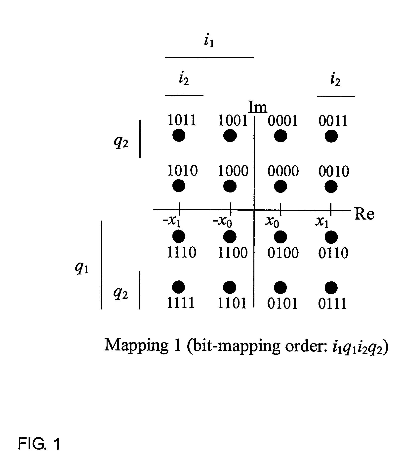
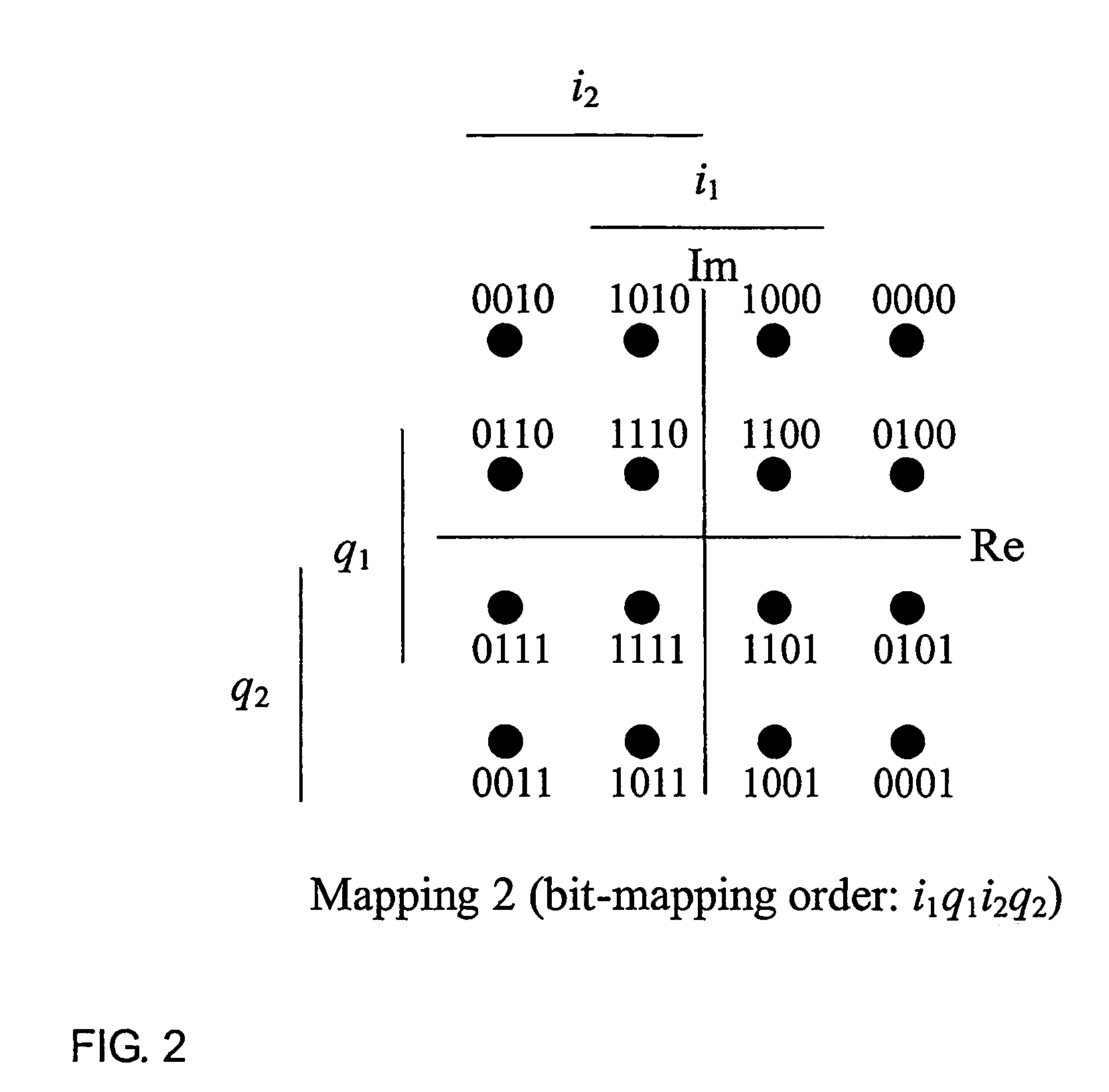
[0019]Depending on the employed modulation format and the actual number of bits mapped onto a single modulation symbol, for a given arbitrary number (N>1) of available diversity branches the quality of the averaging process is different. Averaging in the sense of the present invention is understood as a process of reducing the differences in mean combined bit reliabilities among the different bits of a data symbol. Although it might be that only after using several diversity branches or paths a perfect averaging with no remaining differences is achieved, averaging means in the context of the document any process steps in the direction of reducing the mean combined bit reliability differences. Assuming on average an equal SNR for all available diversity branches, for 16-QAM 4 mappings (4 diversity branches) would be needed to perfectly average out the reliabilities for all bits mapped on any symbol. However, if e.g. only 2 branches are available a perfect averaging is not possible. Hence, the averaging should then be performed on a best effort basis as shown in the example below.

Problems solved by technology

However, if e.g. only 2 branches are available a perfect averaging is not possible.

Method used


Image

  • Constellation rearrangement for transmit diversity schemes
  • Constellation rearrangement for transmit diversity schemes
  • Constellation rearrangement for transmit diversity schemes

Examples


Embodiment Construction

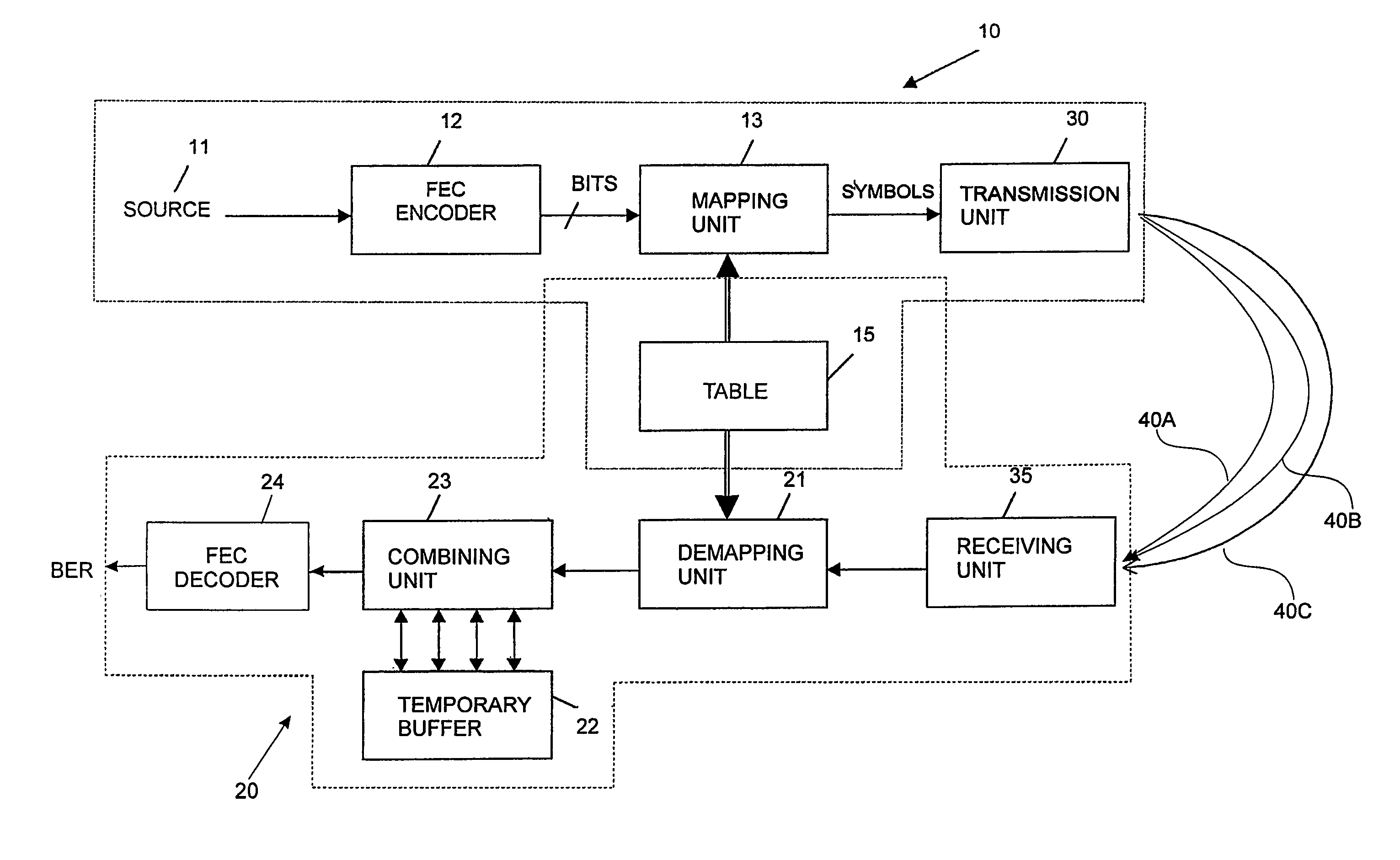
[0027]The following detailed description is shown for a square 16-QAM with Gray mapping. However, without loss of generality the shown example is extendable to other M-QAM and M-PSK (with log2(M)>2) formats. Moreover, the examples are shown for transmit diversity schemes transmitting an identical bit-sequence on both branches (single redundancy version scheme). Then again, an extension to a transmit diversity scheme transmitting only partly identical bits on the diversity branches can be accomplished. An example for a system using multiple redundancy versions is described in copending EP 01127244, filed on Nov. 16, 2001. Assuming a turbo encoder, the systematic bits can be averaged on a higher level as compared to the parity bits.

[0028]Assuming a transmit diversity scheme with two generated diversity branches, which are distinguishable at the receiver (e.g. by different spreading or scrambling codes in a CDMA system, or other techniques of creating orthogonal branches) and a transmi...


PUM


Abstract

A method of transmitting data in a wireless communication system from a transmitter to a receiver, comprising the steps of modulating data at the transmitter using a first signal constellation pattern to obtain a first data symbol. The first data symbol is transmitteds to the receiver using a first diversity branch. Further, the data is modulated at the transmitter using a second signal constellation pattern to obtain a second data symbol. Then, the second data symbol is transmitted to the receiver over a second diversity path. Finally, the received first and second data symbol are diversity combined at the receiver. The invention further relates to a transmitter and a receiver embodies to carry out the method of invention.

Description

FIELD OF THE INVENTION[0001]The present invention relates generally to transmission techniques in wireless communication systems and in particular to a method, transceiver and receiver using transmit diversity schemes wherein the bit-to-symbol mapping is performed differently for different transmitted diversity branches. The invention is particularly applicable to systems with unreliable and time-varying channel conditions resulting in an improved performance avoiding transmission errors.BACKGROUND OF THE RELATED ART[0002]There exist several well known transmit diversity techniques wherein one or several redundancy versions relating to identical data are transmitted on several (at least two) diversity branches “by default” without explicitly requesting (by a feedback channel) further diversity branches (as done in an ARQ scheme by requesting retransmissions). For example the following schemes are considered as transmit diversity:[0003]Site Diversity: The transmitted signal originate...

Claims


Application Information

Patent Timeline
IPC IPC(8): H04B7/02H03M13/25H03M13/29H04B7/06H04B7/08H04J11/00H04L1/00H04L1/06H04L27/36
CPCH04L1/02H04L1/06H04L1/08H04L27/34H04L1/1845H04L1/1893H04L25/067H04L27/0008H04L1/1819H04B7/0842H04L1/0071H04B7/06
Inventor WENGERTER, CHRISTIANGOLITSCHEK ELDER VON ELBWART, ALEXANDERSEIDEL, EIKO
Owner PANASONIC INTELLECTUAL PROPERTY CORP OF AMERICA
Learn More