

Millimeter band signal transmitting/receiving system having function of transmitting/receiving millimeter band signal and house provided with the same
a technology of transmitting/receiving system and millimeter band signal, which is applied in the direction of television system, transmission monitoring, wireless communication, etc., can solve the problems of requiring a higher cost, affecting the quality of the signal, and not being practical in a general house. , to achieve the effect of preventing the difference in frequency and reducing the quality
- Summary
- Abstract
- Description
- Claims
- Application Information
AI Technical Summary
Benefits of technology
Problems solved by technology
Method used
Image

Examples
first embodiment
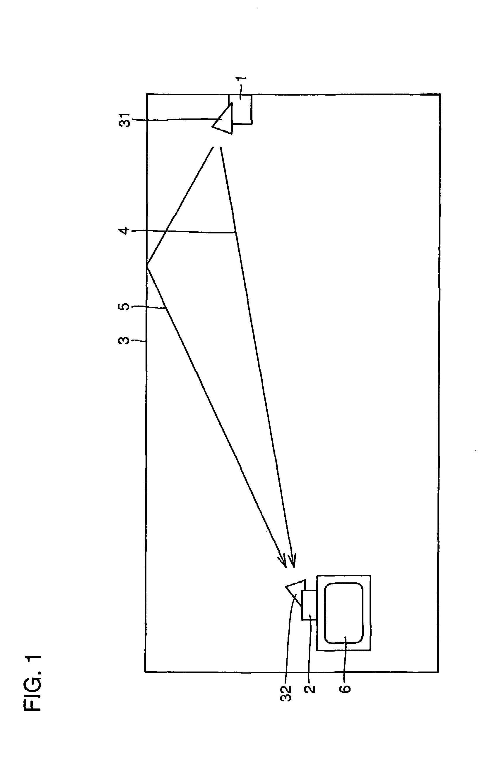
[0055]An arrangement of the first embodiment of the present invention will be described reference to FIG. 1. FIG. 1 is a side view showing a house provided with a millimeter band signal transmitting / receiving system according to the first embodiment of the present invention.
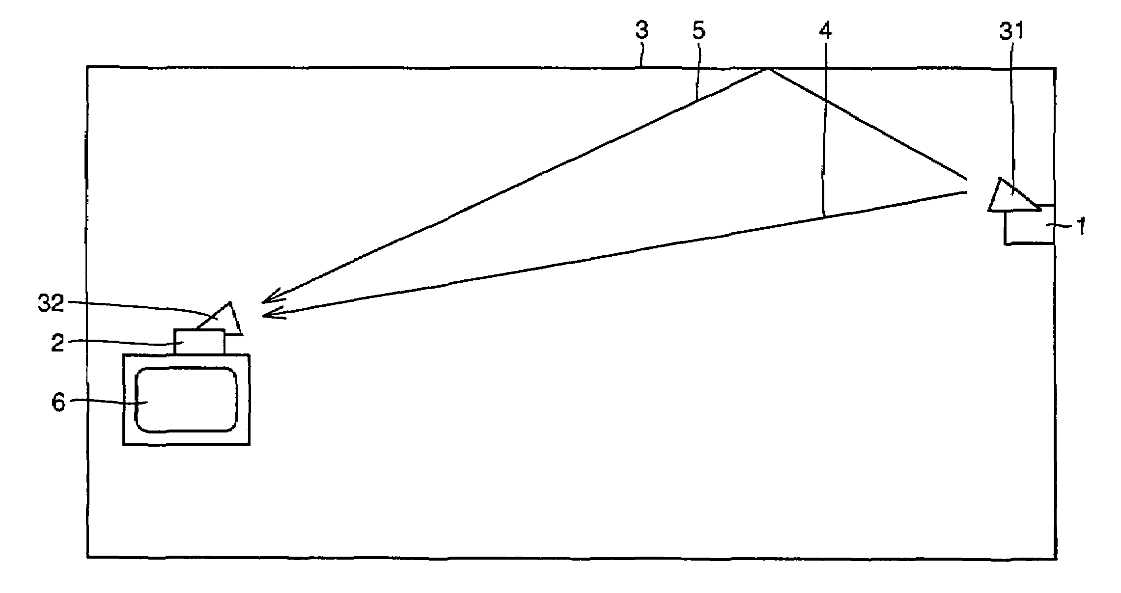
[0056]Shown in FIG. 1 are: a transmitter 1 for transmitting a millimeter-wave video signal; a receiver 2; a ceiling 3 as an example of a structural component defining an internal space of the house; a display (a television or the like) 6 for display of the video signal received by receiver 2: an antenna 31 of transmitter 1; and an antenna 32 of receiver 2.
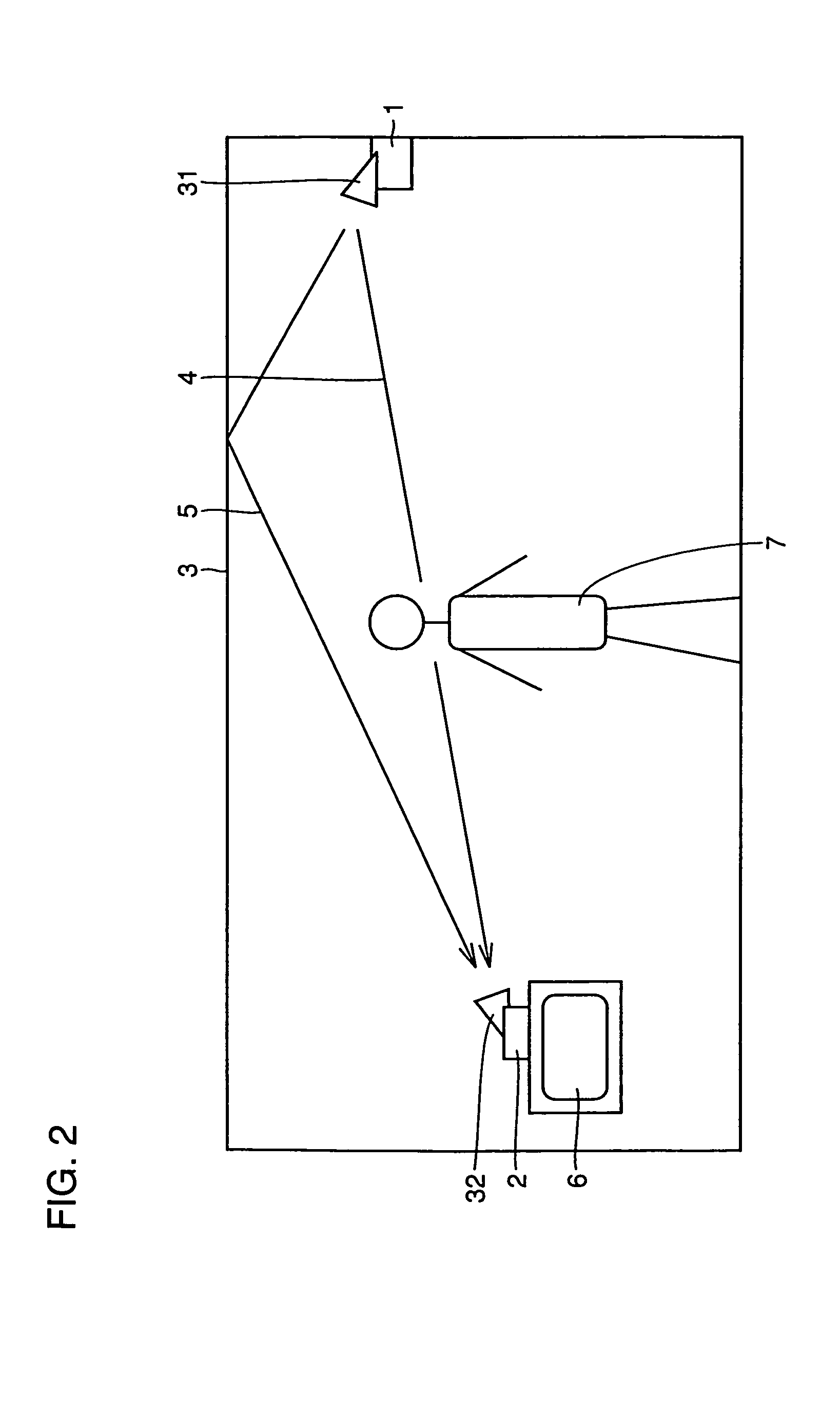
[0057]Ceiling 3 includes a gypsum board. An aperture beam angle for antenna 31 of transmitter 1 is ±30°, and an incident angle from transmitter 1 to ceiling 3 is 70°. Ceiling 3 reflects an output from transmitter 1. In a normal state with no obstruction, a direct wave 4 from transmitter 1 and a reflected wave 5 reflected by ceiling 3 are simultaneously received ...
second embodiment
[0065]An arrangement according to a second embodiment of the present invention will be described with reference to FIG. 3. FIG. 3 is a plan view (a view when seen from the ceiling) of a house provided with a millimeter band signal transmitting / receiving system according to the second embodiment of the present invention.
[0066]Shown in FIG. 3 is a wall surface 8 as an example of a structural component defining an internal space of the house. Wall surface 8 is provided with a reflector 9. A back surface (a surface facing the wall surface of the house) of reflector 9 is covered by a material (for example, an aluminum foil) reflecting a millimeter band signal.
[0067]For example, a picture having on its back surface an aluminum foil is used as reflector 9. As the aluminum foil is applied to the back surface of the picture, reflection of the video signal with the millimeter band is achieved without impairing an appearance of the house.
[0068]As in the first embodiment, also in the second emb...
third embodiment
[0078]An arrangement of a third embodiment of the present invention will be described with reference to FIG. 4. FIG. 4 is a side view showing a house provided with a millimeter band signal transmitting / receiving system according to the third embodiment of the present invention.
[0079]Referring to FIG. 4, two reflectors 90 and 91 are provided in the house. Denoted by a reference numeral 70 is an obstruction, on a propagation path between transmitter 1 and receiver 2. A direct wave from transmitter 1 to receiver 2 is interrupted by obstruction 70.
[0080]Reflectors 90 and 91 reflect signal waves transmitted from transmitter 1. A wave, which is reflected by reflector 90, enters receiver 2. B wave reflected by reflectors 91 and 90 enters receiver 2. In other words, A and B waves simultaneously enter receiver 2.
[0081]As the signal waves transmitted by transmitter 1 enter receiver 2 through the plurality of propagation paths, good video reception is achieved while avoiding a problem associat...
PUM
 Abstract
Description
Claims
Application Information