Therapeutic system

a technology of a therapeutic system and a control device, applied in the field of therapeutic systems, can solve the problems of troublesome simultaneous control of the medical applicator and the observation device, noise in the electro-magnetic wave emitted, and the applicator may distort the image generated by the observation device, etc., and achieve the effect of convenient operation

Inactive Publication Date: 2007-01-16
OLYMPUS CORP
View PDF21 Cites 152 Cited by
  • Summary
  • Abstract
  • Description
  • Claims
  • Application Information

AI Technical Summary

Benefits of technology

[0006]The present invention has been made in view of the foregoing. Its object is to provide a therapeutic system in which the medical applicator and the observation means (e.g., MRI apparatus) can be easily operated at the same time and in which the image generated by the observation means remains clear all the time the medical applicator is used.

Problems solved by technology

Simultaneous control of the medical applicator and the observation means is troublesome.
To make matters worse, the noise in the electro-magnetic waves emitted from the applicator may distort the image generated by the observation means (e.g., MRI device).

Method used


Image

  • Therapeutic system
  • Therapeutic system
  • Therapeutic system

Examples


first embodiment

[0119]The therapeutic system 1 described above, i.e., the invention, is advantageous in the following respects.

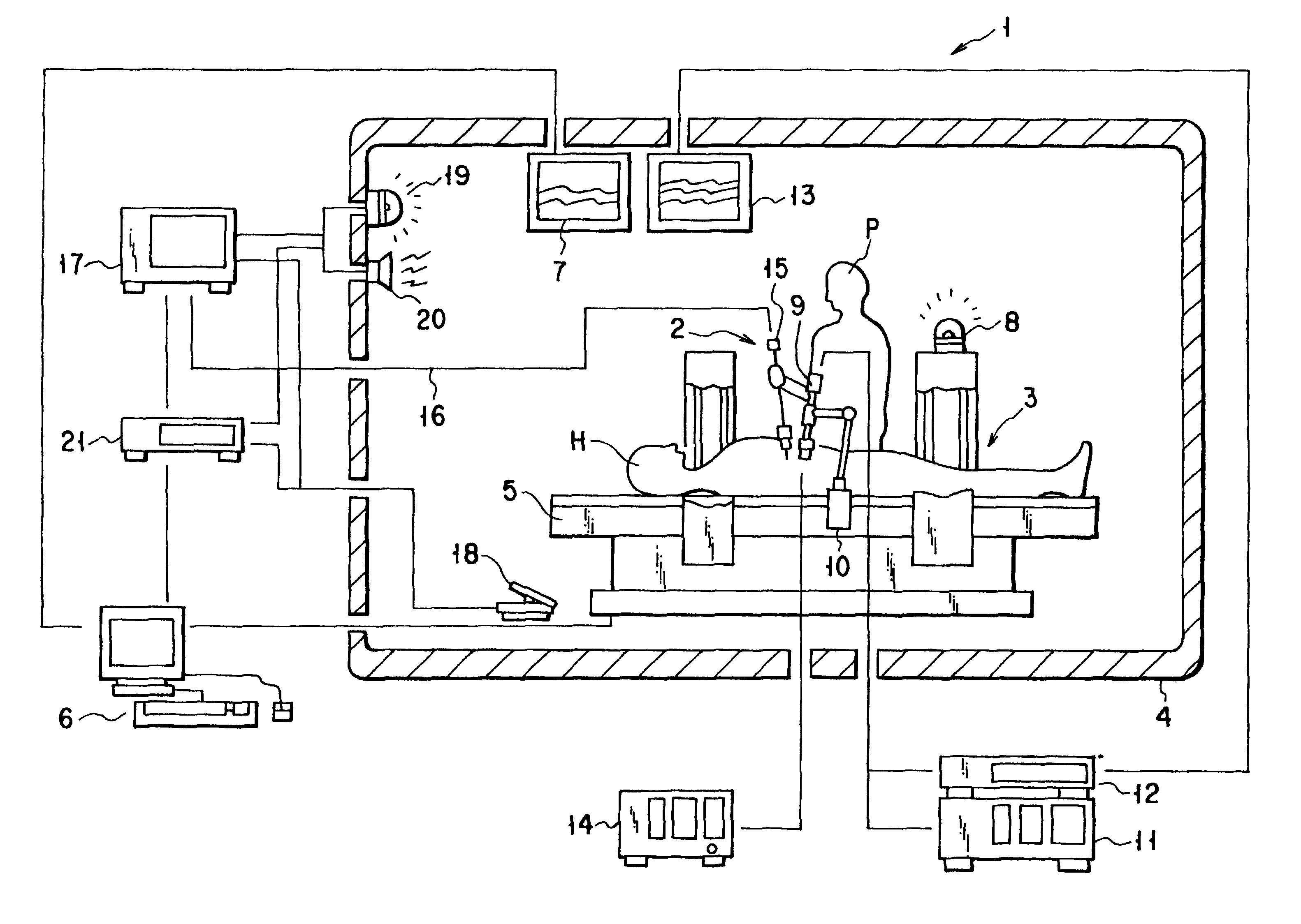
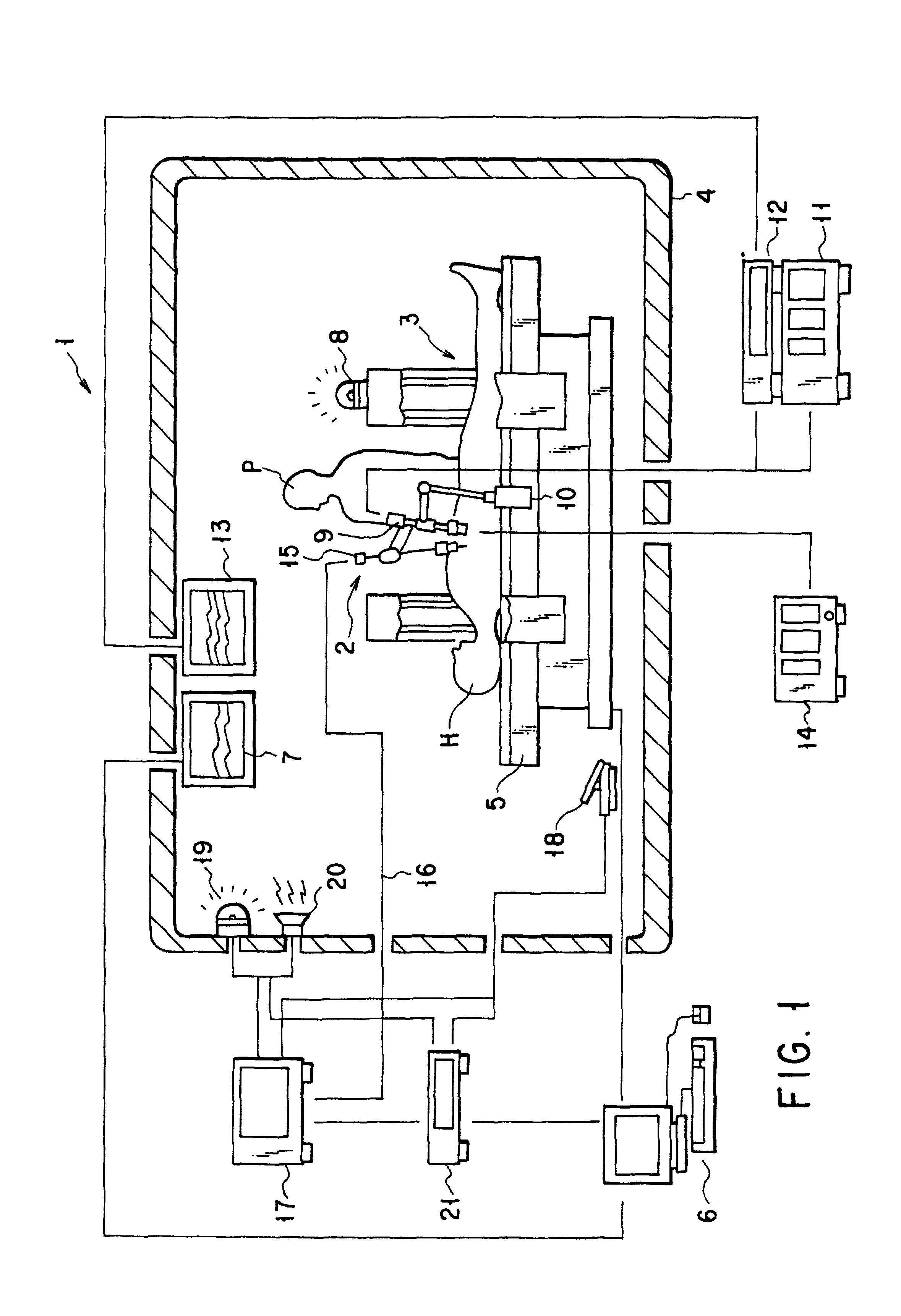
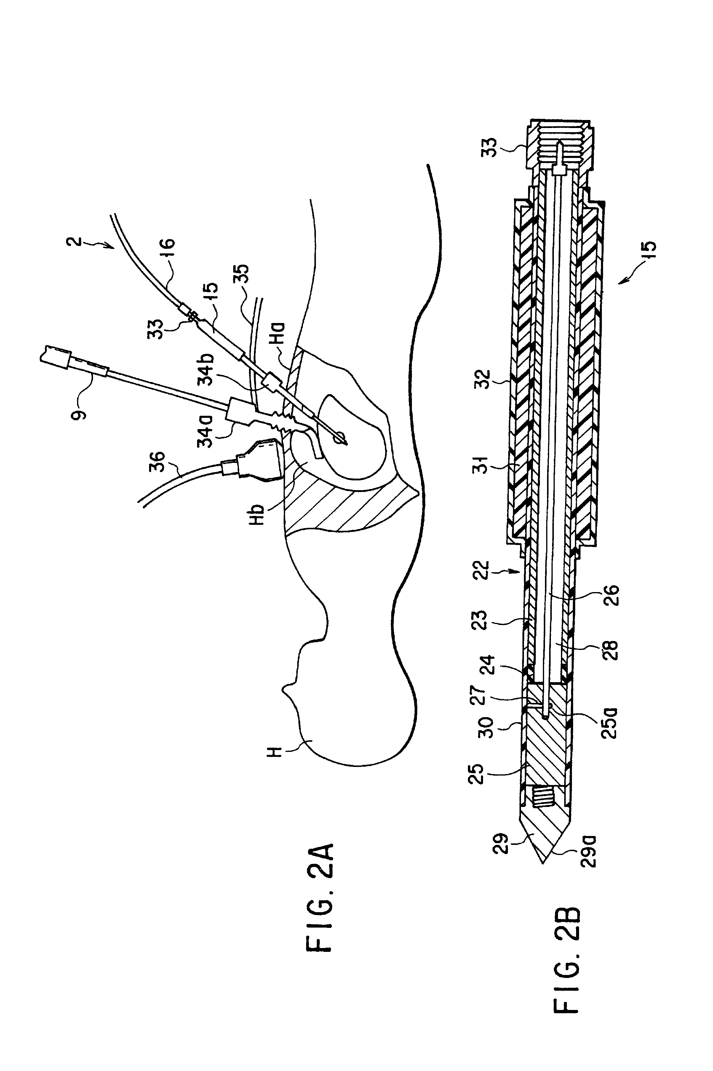
[0120]When the microwave therapeutic apparatus 2 and the MRI apparatus 3 are used simultaneously, the output of the microwave applicator 15, i.e., the energy applied to the affected tissue, is automatically decreased. The noise in the electromagnetic waves applied from the applicator 15 imposes on the MRI image generated by the MRI apparatus 3 can therefore be minimized. The MRI image of the peritoneal cavity Hb, showing the affected tissue, is sufficiently clear even while the microwave therapeutic apparatus 2 is being used. Further, therefore may be also distorted to become unclear, while high-frequency waves are applied to the affected tissue. Since the MRI image is not blurred, showing the affected tissue somewhat larger than it is, there is no possibility that microwaves are applied to anything existing around the affected tissue.

[0121]In the first embodiment, the micr...

second embodiment

[0131]The second embodiment is advantageous in some respects. As shown in FIG. 11, neither the artifact 52 nor the artifact 62 conceals the image of an affected tissue that is treated with microwave (i.e., coagulated region 53). This is because the center of energy-emission (i.e., center part of the MW antenna) is located between the first MR marker 27 and second MR marker 61, both made of solder and resulting in the first artifact 52 and second artifact 62, respectively. As a result, how the living tissue is coagulated can be clearly observed. This enables the doctor to know how the living tissue changes, from the beginning of the microwave therapy he or she is performing by the use of the microwave applicator 15. The safety of the microwave therapy can therefore be enhanced.

[0132]FIG. 12 shows the microwave applicator 15 incorporated in a therapeutic system according to the third embodiment of the invention. The third embodiment differs from the first embodiment (FIGS. 1 to 8) in ...

fifth embodiment

[0137]FIGS. 14 and 15 depict the flexible applicator 91 incorporated in a therapeutic system, which is the present invention. The flexible applicator 91 is designed for accomplishing therapy on affected tissues in the esophageal veins, the bile duct, or the like.

[0138]As shown in FIG. 14, the flexible applicator 91 has an elongated insertion section 94. The insertion section 94 comprises a flexible coaxial cable 95, an MW antenna 96, and an insulating sheath 97. The insertion section 94 is guided into a body cavity through the instrument channel 93 of an MR-compatible endoscope (or an MR endoscope) 92. The flexible coaxial cable 95 is provided in the insertion section 94 and comprises an inner conductor and an outer conductor surrounding the inner conductor. The MW antenna 96, which applies therapeutic energy, is connected to the distal end of the coaxial cable 95. The insulating sheath 97 covers the flexible coaxial cable 95 and the MW antenna 96.

[0139]The MW antenna 96 comprises a...


PUM


Abstract

A therapeutic system comprising a therapeutic applicator for treating living tissues and an observation unit for determining the position of the applicator. The therapeutic energy applied from the applicator to the living tissues is controlled in accordance with data representing the position of the applicator, determined by the observation unit. It is therefore easy to operate the system even if the applicator and the observation unit (e.g., an MRI apparatus) are used at the same time. The image of the living tissues remains clear during the use of the therapeutic applicator.

Description

[0001]This application is a division of application Ser. No. 09 / 266,310, filed Mar. 11, 1999 now U.S. Pat. No. 6,381,483.BACKGROUND OF THE INVENTION[0002]The present invention relates to a therapeutic system comprising a medical applicator to be inserted into a living body and an observation means such as an MRI (Magnetic Resonance Imaging) apparatus.[0003]Generally, a therapeutic system comprises a medical applicator such as a high-frequency instrument and an observation means such as an MRI apparatus. Before the medical applicator is inserted into a patient, the affected tissue within the patient, to which the applicator should be guided, is detected by the observation means. The medical applicator is inserted into the patient and guided to the affected tissue. The applicator is operated, thereby effectively performing high-frequency treatment on the affected tissue.[0004]In the conventional medical system, the applicator and the observation means are driven independently of each ...

Claims


Application Information

Patent Timeline
Patent Type & Authority Patents(United States)
IPC IPC(8): A61B5/05A61B18/12A61B5/055A61B6/12A61B18/18A61B19/00A61N5/02
CPCA61B5/055A61B18/18A61B18/1815A61B19/20A61B6/12A61B2019/5454A61B19/201A61B19/5244A61B2019/5236A61B2019/5276A61B90/10A61B34/20A61B90/11A61B2090/374A61B2090/378A61B2090/3954A61B5/704
Inventor HAREYAMA, NORIHIKONAGASE, TORUHATTA, SHINJI
Owner OLYMPUS CORP
Why Eureka
Try Eureka