Individual slider testing

a slider and individual technology, applied in the field of individual slider testing, to achieve the effect of improving the efficiency of the test system, reducing the number of steps, and being more robus

Inactive Publication Date: 2007-01-23
WESTERN DIGITAL TECH INC
View PDF17 Cites 13 Cited by
  • Summary
  • Abstract
  • Description
  • Claims
  • Application Information

AI Technical Summary

Benefits of technology

[0013]The test system provides many advantages over the prior test procedures. The test system allows for testing of individual sliders which was not feasible with previous test procedures. The slider holder of the test system secures individual sliders in a row form factor to allow for testing of multiple individual sliders at the same time. Because individual sliders are tested, sliders of different designs may be inserted in the slider holder and tested at the same time. Consequently, sliders of different designs can be evaluated under the same test conditions.
[0014]Another advantage is that the test system is more robust against unwanted mechanical stress or ESD. The individual sliders under test are secured in the slider holder throughout the testing procedure. The slider holder is transported between the quasi-static measurement system and the mechanical stress system over the transport system. This eliminates or reduces the need for manually handling the sliders under test.
[0015]Another advantage is that the test system is more efficient than prior test procedures. The test system can be fully automated. The mechanical stress system, the quasi-static measurement system, and the transport system can each be fully automated to reduce testing time. Also, the measurement system is able to perform quasi-static measurements on the sliders simultaneously instead of one at a time.

Problems solved by technology

The test system allows for testing of individual sliders which was not feasible with previous test procedures.

Method used


Image

  • Individual slider testing
  • Individual slider testing
  • Individual slider testing

Examples


Embodiment Construction

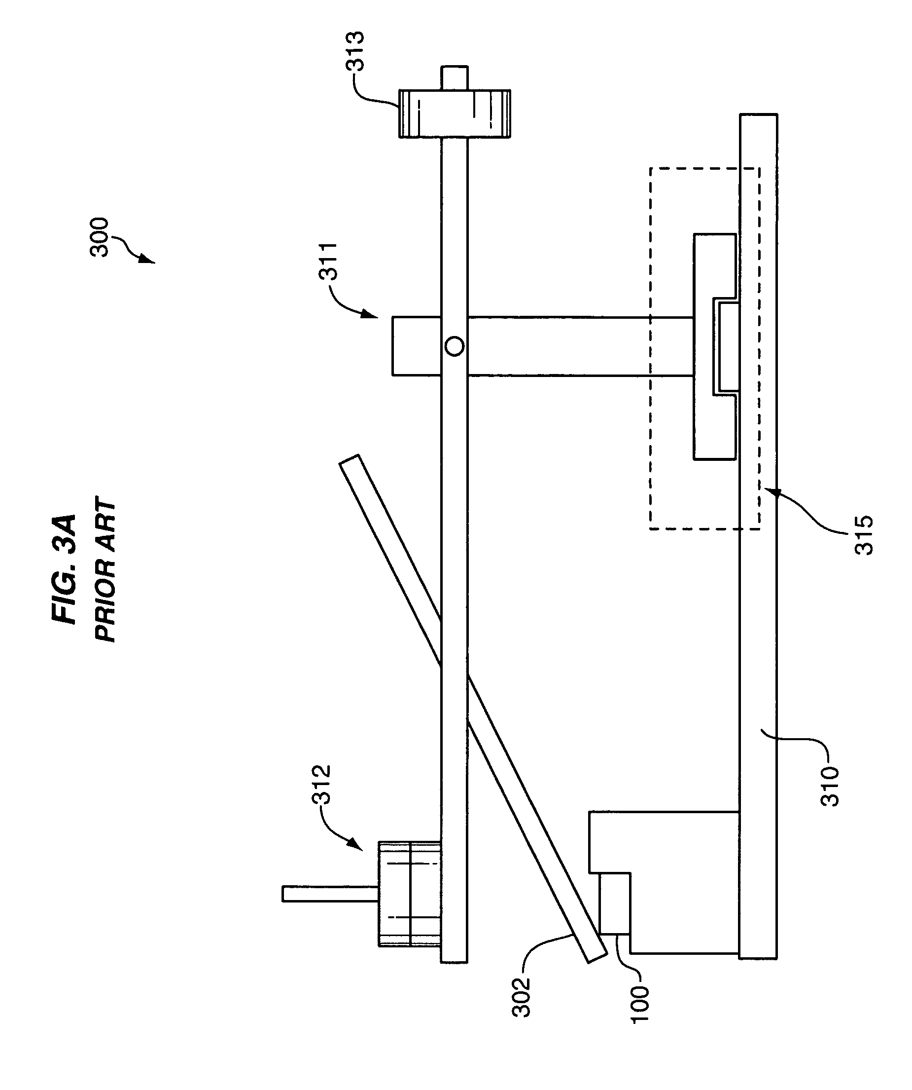
[0027]FIGS. 1, 2, and 3A–B illustrate a current procedure for testing sliders. The current test procedure alternates between applying stress to sliders in a row and performing quasi-static measurements to determine the effects of the applied stress on the sliders.

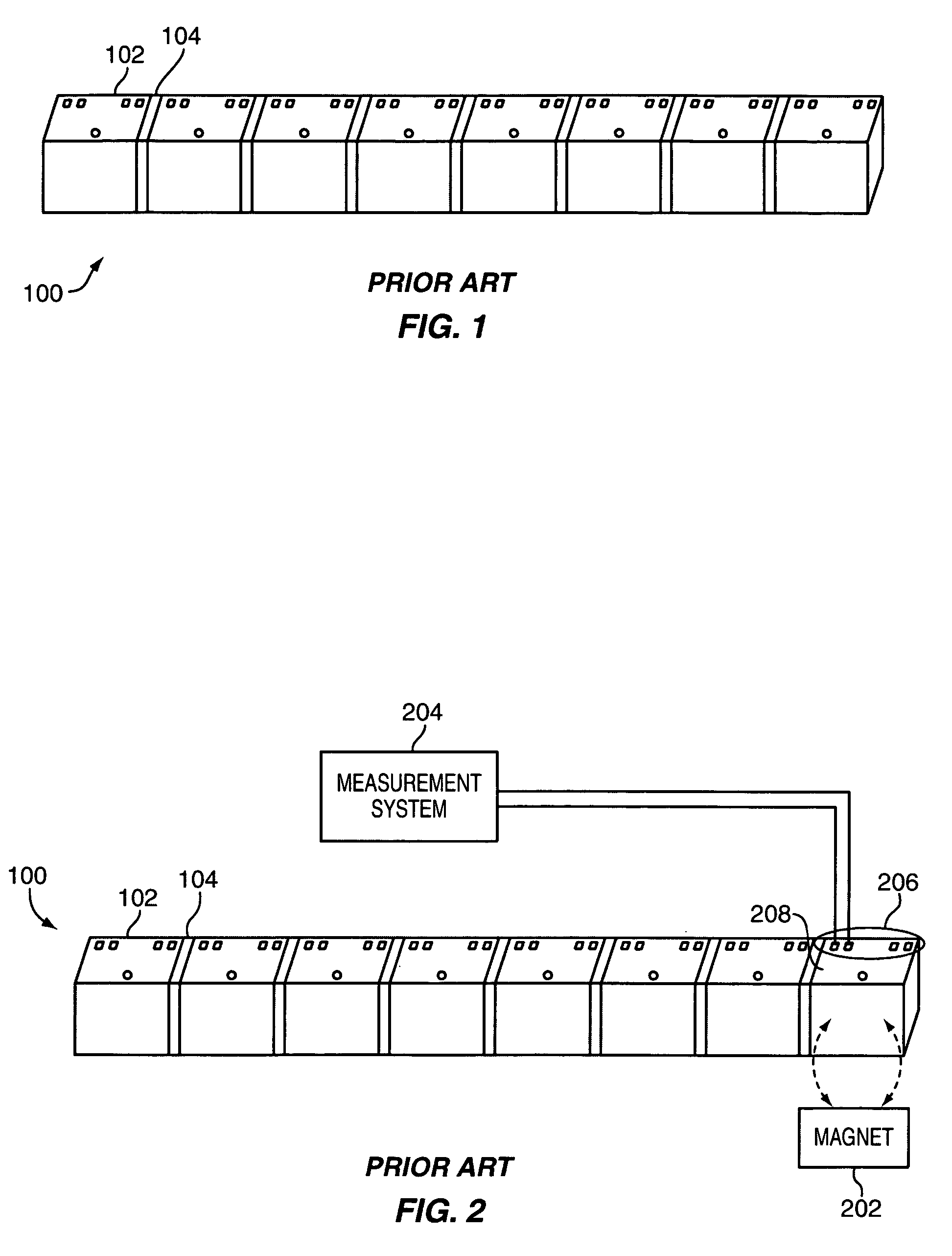
[0028]FIG. 1 illustrates an attached row 100 of sliders that has been cut from a wafer. Row 100 includes a plurality of sliders 102 connected by kerfs 104. Although eight sliders are shown, a typical row may include many more sliders.

[0029]To test the sliders, a test operator performs a quasi-static measurement on each slider 102 in row 100 one at a time. FIG. 2 illustrates a quasi-static measurement for a row of sliders. The test operator positions a first slider in the row 100 of sliders proximate to a magnet 202 of a quasi-static measurement system. The test operator then lands a measurement system 204 of the quasi-static measurement system on conductive pads 206 on the deposit end 208 of the first slider to perform quas...


PUM

PropertyMeasurementUnit
widthaaaaaaaaaa
temperatureaaaaaaaaaa

Abstract

Systems and methods of testing individual sliders are disclosed. One embodiment is a test system that includes a mechanical stress system, a quasi-static measurement system, a transport system, and a slider holder. The individual sliders to be tested are aligned in a row in the slider holder, and the slider holder secures the sliders. The measurement system performs quasi-static measurements on sliders in the slider holder simultaneously. The transport system then transports the slider holder to the mechanical stress system. The mechanical stress system applies mechanical stress to the sliders in slider holder. The transport system then transports the slider holder again to the quasi-static measurement system. This process repeats a desired number of times to complete testing.

Description

BACKGROUND OF THE INVENTION[0001]1. Field of the Invention[0002]The invention is related to the field of magnetic storage devices, and in particular, to systems and methods for testing individual sliders for magnetic storage devices.[0003]2. Statement of the Problem[0004]Many computer systems use disk drives for mass storage of information. Disk drives typically include one or more sliders positioned proximate to a storage media. The sliders include read and write elements that read from and write to the storage media. One type of slider includes a Giant Magneto-Resistive (GMR) read element. To read data from the storage media, the storage media spins and magnetic data in the media generates a localized magnetic field. The magnetic field modulates the resistance of a magneto-resistive (MR) element in the slider. The change in resistance of the MR element is detected by passing a sense current through the MR element and then measuring the change in voltage across the MR element. The ...

Claims


Application Information

Patent Timeline
Patent Type & Authority Patents(United States)
IPC IPC(8): G01N3/02G01R33/12
CPCG11B5/3166G11B5/3169G11B5/455G11B5/3173G11B2005/0016G11B5/3189
Inventor LUO, JIH-SHIUANSANAYEI, ALI
Owner WESTERN DIGITAL TECH INC
Why Eureka
Try Eureka