Heavy duty pneumatic radial tire with carcass ply winding-up portion

a radial tire and heavy duty technology, applied in the direction of tyre beads, transportation and packaging, other domestic articles, etc., can solve the problems of deformation, inducing falling, or loosing, inducing damage, etc., and achieve the effect of enhancing bead durability and maintaining excellent bead durability in the bead wind structur

Inactive Publication Date: 2007-01-23
SUMITOMO RUBBER IND LTD
View PDF11 Cites 4 Cited by
  • Summary
  • Abstract
  • Description
  • Claims
  • Application Information

AI Technical Summary

Benefits of technology

[0018]Consequently, it is possible to provide a heavy duty pneumatic radial tire having excellent durability, in which a damage at the tip of the carcass ply, generation of falling out (blowing) and deficient molding can be suppressed.
[0020]In this manner, it is possible to enhance the stability of the bead core and accurately set the shape and position of the winding-up portion in the carcass cord to be wound around the bead core by using the wide bead core. Consequently, it is easy to stably hold the distance La at 5 mm to 15 mm (preferably 12 mm) and the distance Lb at 1 mm to 5 mm with ease, thereby enhancing the durability of the bead.
[0021]According to the invention as claimed in claim 3, a cord layer passing through the outer surface of the winding-up portion is inclined in a diameter increasing direction inward in a tire axial direction. Consequently, it is possible to prevent any easy generation of creases or wrinkles at the carcass ply in the vicinity of the outer end of the winding-up portion or any variation at the carcass cord. Furthermore, it is possible to prevent any vulcanization due to air enclosure between the winding-up portion and the bead core by the cord layer. Thus, it is possible to provide a stable and firm tire.
[0023]In this manner, a heavy duty pneumatic radial tire, in which excellent bead durability in a bead wind structure can be provided.
[0025]In this manner, the heavy duty pneumatic radial tire is provided, in which the excellent bead durability in the bead wind structure can be maintained by restricting the tensile strength and implanting number of carcass cords at the winding-up portion also in the case where the tip is separated from the bead core.
[0026]Since the invention as claimed in any one of claims 8 to 11 is provided with a feature of each of materials, the object is to provide the heavy duty pneumatic radial tire, in which the bead durability can be enhanced by suppressing a damage at the tip and / or a damage at the inner end in the tire axial direction of the bead core.

Problems solved by technology

As a result, there may be liable to arise problems of deficient molding due to air remainder such as generation of a cavity between the winding-up portion a1 and the bead core b.
However, if the winding-up portion a1 is too separated from the bead core b even when the filled rubber is used, the stress exerted on the tip of the winding-up portion a1 becomes large, not to suppress a damage and not to increase the locking force, thereby easily inducing falling up, or loosing.
In contrast, if the winding-up portion a1 is not so separated from the bead core b, an impact exerted on the tip becomes large, thereby easily inducing a damage.
Moreover, the folding-back remains strong, thereby making it difficult to sufficiently suppress the deficient molding.
As a consequence, the problems experienced by the tire in the prior art cannot be solved.
Additionally, as soon as the carcass ply becomes easy to be moved in the falling out direction since the locking force to the winding-up portion a1 becomes weakened owing to the separation, the carcass ply is liable to slide on the bead core b at an inner end position Q in the tire axial direction of the bead core b. Furthermore, it has been found that a damage is likely to occur at the position Q, since a topping rubber of the carcass cord is liable to be split in combination with a strong press-contact force with the bead core b.

Method used


Image

  • Heavy duty pneumatic radial tire with carcass ply winding-up portion
  • Heavy duty pneumatic radial tire with carcass ply winding-up portion
  • Heavy duty pneumatic radial tire with carcass ply winding-up portion

Examples


example 1

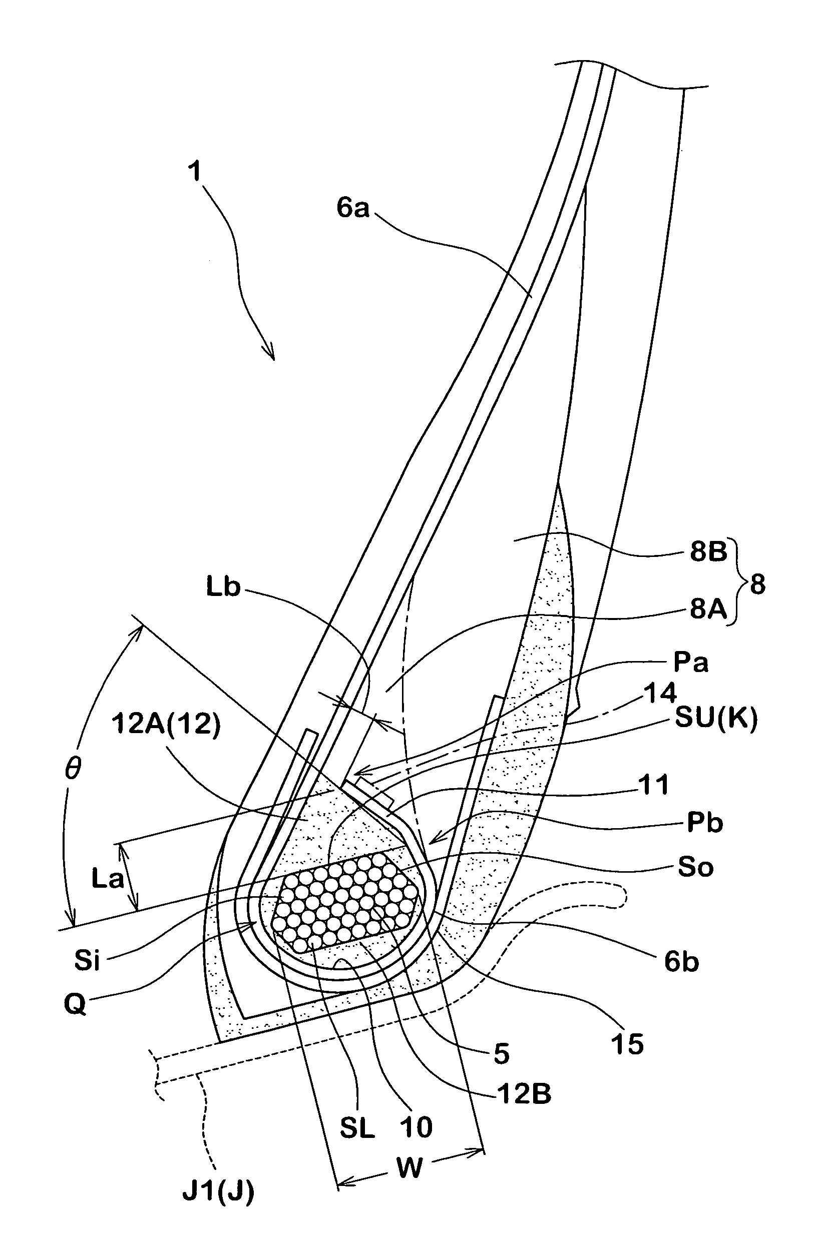
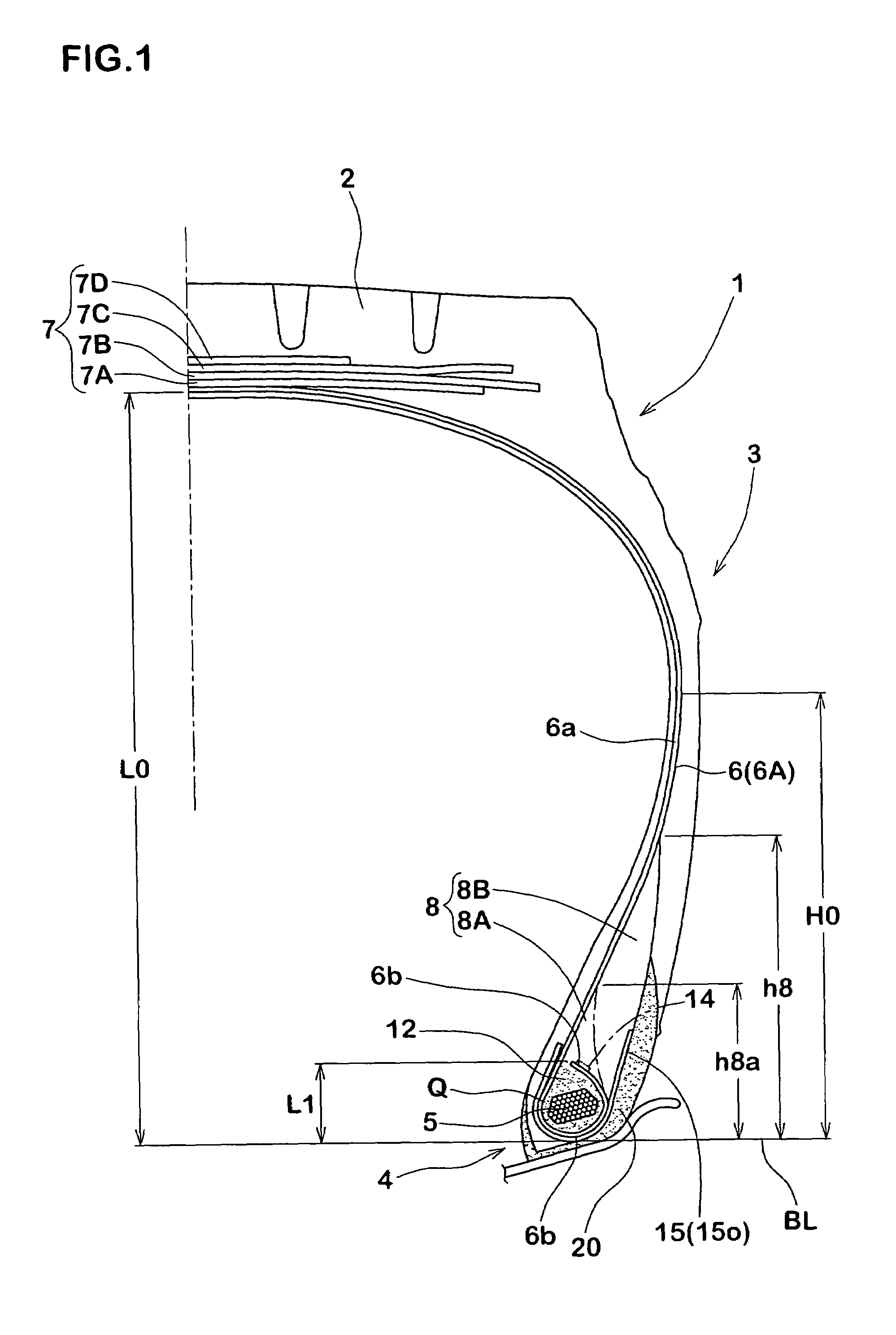
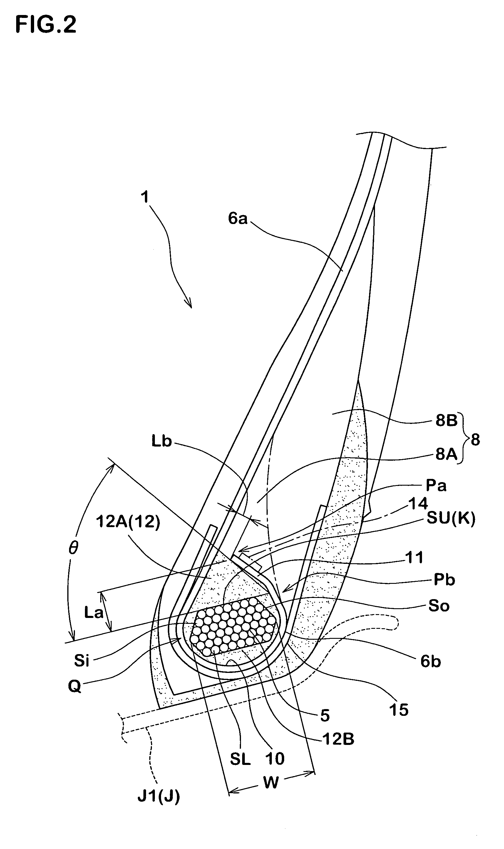
[0092]A heavy duty tire (11R 22.5), having the structure shown in FIG. 1 based on specifications shown in Table 1 (without any coated cord layer) and a heavy duty tire (11R 22.5) based on specifications shown in Table 2 were prototyped, and further, the bead durabilities of the prototyped tires were measured for comparison. Here, specifications other than those shown in Tables were the same as each other.

[0093]Incidentally, the prior art tire had a structure, in which a carcass winding-up portion a2 was wound along an outside surface of a bead apex rubber c, as shown in FIG. 11, wherein a height hb from a bead base line at the upper point of the bead apex c was 85 mm.

(1) Bead Durability:

General Bead Durability:

[0094]The tire was made to travel at a speed of 30 km / h under the conditions of a rim (7.50×22.5), an inner pressure (700 kPa) and a vertical duty (27.25 kN×3) by a drum test machine. A traveling time until a damage occurred at the bead was indicated with an index in the prio...

example 2

[0099]A heavy duty pneumatic radial tire having the basic configuration shown in FIG. 5 and a size of 11R 22.5 was prototyped based on specifications shown in Table 3, and further, tests were carried out with respect to drum durability and finishing accuracy. In regard to the distances La and Lb, a tire meridian cross section of a tire / rim assembly was photographed by a CT scanner in a normal state, and as a result, an average value of values at 10 points on the circumference of the tire was examined. A test method is as follows:

[0100]A test tire was disposed in a regular rim with the application of an inner pressure of 800 kPa, and then, was made to travel on a drum at a speed of 20 km / h and a vertical duty of 75 kN. A traveling time was measured until a damage occurred, wherein a traveling time in a comparative example was used as an index of 100. The greater the value, the more excellent the durability.

[0101]A test tire was disposed in a regular rim with the application of an inn...

example 3

[0106]A heavy duty tire (11R 22.5) having the structure shown in FIG. 1 based on specifications shown in Table 4 and a heavy duty tire (11R 22.5) having the structure shown in FIG. 1 based on specifications shown in Table 5 were prototyped, and further, the bead durabilities of the prototyped tires were measured for comparison. Here, specifications other than those shown in Tables were the same as each other. No coated cord layer was provided in the tire.

[0107]Incidentally, the prior art tire had a structure, in which a carcass winding-up portion was wound along an outside surface of a bead apex rubber, as shown in FIG. 11, wherein the height hb from a bead base line at top of the bead apex rubber c was 65 mm.

(1) Bead Durability:

General Bead Durability:

[0108]The tire was made to travel at a speed of 30 km / h under the conditions of a rim (7.50×22.5), an inner pressure (700 kPa) and a vertical duty (27.25 kN×3) by a drum test machine. A traveling time until a damage occurred at the b...


PUM

PropertyMeasurementUnit
widthaaaaaaaaaa
tensile strengthaaaaaaaaaa
temperatureaaaaaaaaaa

Abstract

A heavy duty pneumatic radial tire includes a carcass ply, in which a ply folding portion folding a bead core is successively disposed in a ply body. The ply folding portion includes a main portion folded along the bead core, and a winding-up portion extending continuously to the main portion and apart from the bead core. The winding-up portion extends with an inclination of an angle θ in a direction in which a diameter is increased inward in the tire axial direction, the angle θ being set to 20 to 65 degrees with respect to an upper surface in the radial direction of the bead core, a distance La from the upper surface in the radial direction of the bead core at the inner end point of the winding-up portion being set to 5 mm to 15 mm, and a distance Lb between the inner end point of the winding-up portion and the ply body being set to 1 mm to 5 mm.

Description

[0001]This Nonprovisional application claims priority under 35 U.S.C. § 119(a) on Patent Application No(s). 2003-395922; 2003-410760; 2003-423348; and 2003-423349 filed in Japan on Nov. 26, 2003; Dec. 9, 2003; Dec. 19, 2003; and Dec. 19, 2003, respectively, the entire contents of which are hereby incorporated by reference.BACKGROUND OF THE INVENTION[0002]1. Field of the Invention[0003]The present invention relates to a heavy duty pneumatic radial tire for use in a truck, a bus and the like, in which the durability of a bead is enhanced while reducing a weight by improving the structure of a winding-up portion of a carcass.[0004]2. Description of the Related Art[0005]As shown in FIG. 8, a carcass has been recently provided with a main unit disposed between bead cores b, b and a ply folding portion a wound around the bead core. Such a ply folding portion a consists of a main portion, which is folded along an inside surface in a tire axial direction, a lower surface in a radial directi...

Claims


Application Information

Patent Timeline
Patent Type & Authority Patents(United States)
IPC IPC(8): B60C1/00B60C15/00B60C15/04B60C15/06B60C9/08B29D30/32
CPCB29D30/32B60C15/0027B60C15/04B60C15/06B29D2030/3285Y10T152/10819Y10T152/10846Y10T152/10855Y10T152/10828B60C15/0607
Inventor SUGIYAMA, NAOKINISHI, MINORUOHTSUKI, HIROTOSHI
Owner SUMITOMO RUBBER IND LTD
Why Eureka
Try Eureka