Two-stage pressure relief valve

a pressure relief valve and two-stage technology, applied in the direction of positive displacement liquid engine, fluid coupling, bend, etc., can solve the problems of excessive heat generated by the high flow rate through the hydraulic system, no way to correct a failed pump, and requires additional space on the aircraft, so as to achieve less expensive, less power, and less heat generation.

Active Publication Date: 2007-01-23
BELL HELICOPTER TEXTRON INC
View PDF10 Cites 33 Cited by
  • Summary
  • Abstract
  • Description
  • Claims
  • Application Information

AI Technical Summary

Benefits of technology

[0018]Therefore, it is an object of the present invention to provide a hydraulic system in which solenoid operated shut off valves and oversized heat exchangers are not required.
[0020]The present invention provides significant advantages, including: (1) it has the ability to provide limited hydraulic power to the aircraft following a pump compensator failure; (2) it is more reliable than solenoid operated bypass valves; (3) it is less expensive than oversizing heat exchangers or adding solenoid operated bypass valves; and (4) it weighs less than oversized heat exchangers and solenoid operated bypass valves.

Problems solved by technology

In most aircraft, there is usually no way to correct a failed pump.
However, pressure relief valves are utilized in aircraft hydraulic systems to reduce high system pressures that result from pump compensators that fail and remain stuck in the maximum flow position.
When pump compensators fail and remain in the maximum flow position, excessive heat is generated by the high flow rates through the hydraulic system.
This method requires additional space on the aircraft and adds a significant amount of weight to the aircraft.
Once the solenoid operated bypass valve or shut-off valve is activated, all hydraulic power from that system is lost.
Solenoid operated bypass valves and shut-off valves are relatively unreliable, and require an external electrical power source.
This increases their probability of failure.
In addition, this method can result in the failure of a hydraulic system as a result of an electrical short.
Under this type of failure, the pump flow exceeds system demand, resulting in the system pressure exceeding the allowable design limit.
Although the pressure relief valve protects the hydraulic system from damage due to over pressurization, relief valve operation can induce a second equally critical problem: hydraulic system overheating.
However, following a pump compensator failure and resultant opening of a pressure relief valve, system pressure typically increases by 20–30%.
The current methods of preventing hydraulic systems from overheating following pump compensation failures do not adequately solve the problem.
Solenoid operated bypass valves or shut-off valves are unreliable, require an electrical power source, and add weight to the system.
Oversizing the heat exchangers is expensive, requires additional space, and adds weight to the system.

Method used


Image

  • Two-stage pressure relief valve
  • Two-stage pressure relief valve
  • Two-stage pressure relief valve

Examples


Embodiment Construction

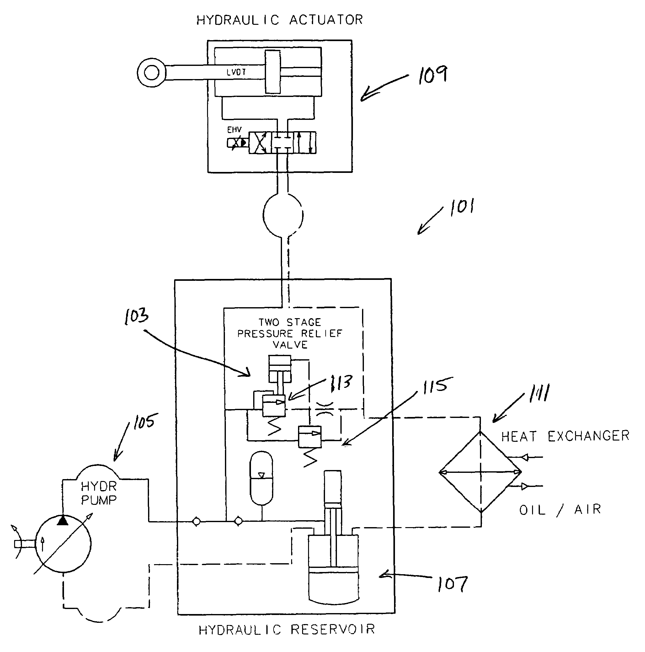
[0029]Referring to FIG. 5 in the drawings, a hydraulic system 101 having a two-stage pressure relief valve 103 for preventing damage resulting from hydraulic pump compensator failure according to the present invention is illustrated. Hydraulic system 101 includes a variable displacement hydraulic pump 105, a hydraulic reservoir 107, a hydraulic actuator 109, an optional heat exchanger 111, and two-stage pressure relief valve 103.

[0030]Pressure relief valve 103 operates in two distinct stages: a first stage 113, and a second stage 115. First stage 113 of pressure relief valve 103 opens when the system pressure exceeds the normal operating pressure and relieves all pressure increases up to a threshold pressure level, which is preferably up to about 30% over the normal operating pressure. With this capacity, first stage 113 can relieve increases in pressure that result from pump compensators failing in the fully open position. In this manner, first stage 113 protects hydraulic system 1...


PUM


Abstract

A two-stage pressure relief valve for use with hydraulic systems is disclosed. The two-stage pressure relief valve has a first stage that relieves increases in hydraulic system pressure over the normal operating pressure and up to a selected threshold pressure level, and a second stage that brings the hydraulic system pressure down to a selected reduced operating pressure that is below the normal operating pressure in response to increases in the operating pressure over the threshold pressure level.

Description

BACKGROUND[0001]1. Field of the Invention[0002]The present invention relates to hydraulic power systems using pumps with pressure compensators.[0003]2. Description of Related Art[0004]In aircraft hydraulic systems, hydraulic pressure is maintained at a constant magnitude under changing flow demands by using pumps with pressure compensation mechanisms. For each pump, as hydraulic system flow demands change, the compensator adjusts the pump displacement by sensing and responding to the system pressure. If the system pressure drops, the compensator increases the pump displacement, thereby increasing flow and boosting the system pressure. If the system pressure increases, the compensator decreases the pump displacement, thereby decreasing flow and lowering the system pressure.[0005]In most aircraft, there is usually no way to correct a failed pump. In pump failure situations, the failed pump is ignored and a backup pump is used. However, pressure relief valves are utilized in aircraft h...

Claims


Application Information

Patent Timeline
Patent Type & Authority Patents(United States)
IPC IPC(8): F04B1/26F15B21/02F16D31/02F04B49/24F04F1/00F04B1/20F04B3/00
CPCF04B1/2042F04B3/006F15B13/024F15B20/007F15B2211/8752F15B2211/50518F15B2211/511F15B2211/5157F15B2211/528F15B2211/20546Y10T137/2761
Inventor FENNY, CARLOS A.BRYAN, DARREL B.SCHULTZ, DAVID P.
Owner BELL HELICOPTER TEXTRON INC
Why Eureka
Try Eureka