Pick up cap for LGA connector assembly

a technology of lga connectors and pick-up caps, which is applied in the direction of coupling device connections, electrical apparatus construction details, engagement/disengagement of coupling parts, etc., can solve the problems of reducing the reliability of the soldering connection between the contacts of the lga connector and the pcb, and the sodering process is prone to be difficul

Inactive Publication Date: 2007-01-23
HON HAI PRECISION IND CO LTD
View PDF1 Cites 14 Cited by
  • Summary
  • Abstract
  • Description
  • Claims
  • Application Information

AI Technical Summary

Benefits of technology

[0009]Accordingly, an objective of the present invention is to provide a pick up cap for an LGA connector assembly, wherein when the connector is soldering to a PCB with a infrared emitter, the pick up cap can guarantee that the tin between the contacts of the LGA connector and the PCB heated evenly.
[0010]To achieve the above-mentioned objective, an LGA connector assembly in accordance with a preferred embodiment of the invention comprises an LGA connector and a pick up cap. The connector has an insulative housing which defines a multiplicity of passageways, a corresponding number of electrical contacts received in the passageways, and a metal clip. The housing defines a generally rectangular cavity for receiving an electronic package such as CPU therein. The clip is disposed on the housing to press the CPU upon the contacts. The clip defines a rectangular window in the middle thereof. Around the window there are two opposite sidepieces and two opposite urging sides. A pick up cap is detachably mounted on the clip. The pick up cap has a rectangular planar body which defines two opposite end portions and two opposite side portions, each of the two side portions has a recess. When the pick up cap is mounted on the clip, the two end portions engage with two opposite sidepieces, and there defines two rifts between two urging sides and two side portions, then use a vacuum suction device to suck the top surface of the pick up cap and put the connector to a predetermined position in the PCB. Because each of the two opposite side portions has a recess and there are two rifts between the side portions and urging sides. When using an infrared emitter, from an upper position, to heat up the tin under the passageways for soldering the connector onto the PCB, heat air can easily go through the recesses and the rifts between the side portions and urging sides, and then through the passageways to reach the tin under the passageways, in this way, the tin can be heated up evenly, therefore, a reliable soldering connection between the connector and the PCB can be achieved.

Problems solved by technology

However, with regard to the LGA connector whose passageways are centralized and dense, the soldering process is prone to be difficult. FIG. 5 illustrates a conventional LGA connector 8 for electrically connecting a CPU to a PCB, which has an insulative housing with a plurality of passageways (now shown) therein, a corresponding number of contacts received in the passageways, a metal stiffener 81 partly covering the housing to enforce the housing, a lever 83 pivotably attached to an end of the stiffener 81, and a metal clip 82 pivotably mounted onto an opposite end of the stiffener 81.
After the pick up cap 9 being assembled onto the LGA connector 8, there are many passageways (not shown) covered by the pick up cap, while the infrared emitter is heating up the tin between the contacts of the BTB connector and the PCB, the tin can not be heated evenly, this will certainly decrease the reliability of the soldering connection between the contacts of the LGA connector and the PCB.

Method used


Image

  • Pick up cap for LGA connector assembly
  • Pick up cap for LGA connector assembly
  • Pick up cap for LGA connector assembly

Examples


Embodiment Construction

[0017]Reference will now be made to the drawings to describe the present invention in detail.

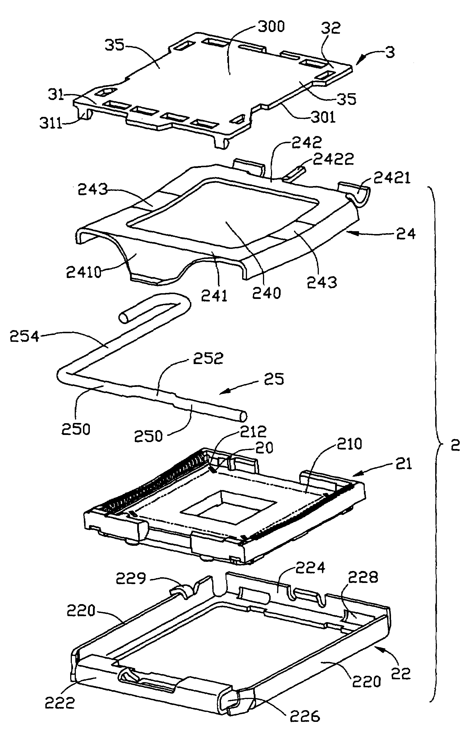
[0018]FIG. 1 shows an exploded, isometric view of an LGA connector assembly in accordance with a preferred embodiment of the present invention. The LGA connector assembly has an LGA connector 2 and a generally rectangular pick up cap 3. The pick up cap 3 can be pre-attached on the connector 2 for provision of a flat top surface 300 to be sucked by a vacuum suction device, thereby facilitating manipulating the LGA connector assembly onto a predetermined position in the PCB (not shown).

[0019]The connector 2 has an insulative housing 21 which defines a generally rectangular cavity 210 in a middle thereof. The cavity 210 is used for receiving an electronic package such as an CPU (not shown) therein. A multiplicity of passageways 212 is defined under the cavity 210, the passageways 212 receiving a corresponding number of contacts 20 therein. A metal stiffener 22 partly covers the housing 21 to en...


PUM


Abstract

A pick up cap for an LGA connector, the connector has a housing which defines a multiplicity of passageways, a plurality of electrical contacts received in the passageways, a metal clip and a pick up cap. The clip defines a rectangular window in the middle thereof. Around the window there are two opposite sidepieces and two opposite urging sides. The pick up cap is detachably mounted on the clip. The pick up cap has a rectangular planar body which defines two opposite end portions and two opposite side portions. Each of the two side portions has a waist. When the pick up cap is mounted on the clip, two end portions engage with two opposite sidepieces, two opposite sidepieces and two opposite end portions cooperatively define two rifts therebetween.

Description

BACKGROUND OF THE INVENTION[0001]1. Field of the Invention[0002]The present invention relates to a land grid array (LGA) connector assembly which has an LGA connector and a pick up cap being mounted to the connector for provision of a smooth flat top surface for being sucked by a vacuum suction device, thereby facilitating mounting the LGA connector assembly onto a substrate circuit such as a printed circuit board (PCB).[0003]2. Description of the Prior Art[0004]On many mass production lines, vacuum suction technology widely are used in processes of mechanical assembly. A typical process is: mounting a pick up cap onto an electronic component such as an LGA connector, using a vacuum suction device to suck the pick up cap and position it to a predetermined position on a substrate circuit with tin pre-attached in advance. The substrate circuit can be a printed circuit board PCB. When the LGA connector is positioned on the predetermined position, an infrared emitter is used to heat up ...

Claims


Application Information

Patent Timeline
Patent Type & Authority Patents(United States)
IPC IPC(8): H01R13/62H01R12/00H01R13/44H01R13/60H01R43/00
CPCH05K7/1061H05K13/0408Y10S439/94
Inventor MA, HAO-YUNLIAO, FANG-JWU
Owner HON HAI PRECISION IND CO LTD
Why Eureka
Try Eureka