Evaporation device

Inactive Publication Date: 2007-01-23
B G NEGEV TECH & APPL LTD +1
View PDF11 Cites 43 Cited by
  • Summary
  • Abstract
  • Description
  • Claims
  • Application Information

AI Technical Summary

Benefits of technology

[0007]The present invention makes use of the known phenomenon that increasing the surf

Problems solved by technology

These ponds present an environmental challenge, as leakage from such ponds can lead to serious groundwater contamination.
The requirements of environmental authorities regarding the quality of lining of such ponds are becoming more stringent and therefore the costs ther

Method used


Image

  • Evaporation device
  • Evaporation device
  • Evaporation device

Examples


Embodiment Construction

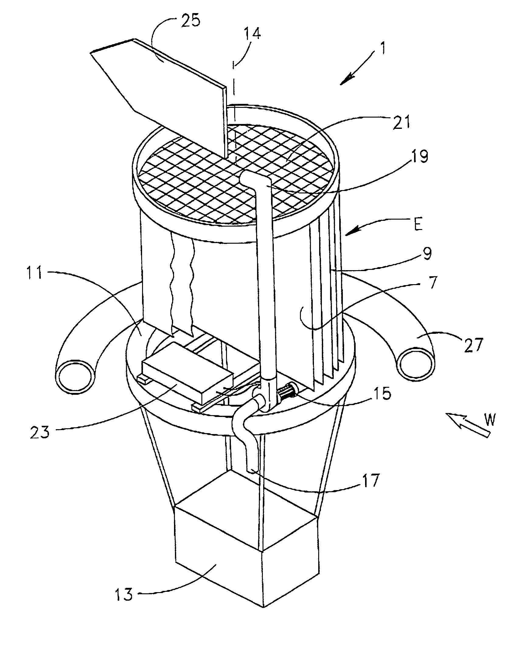
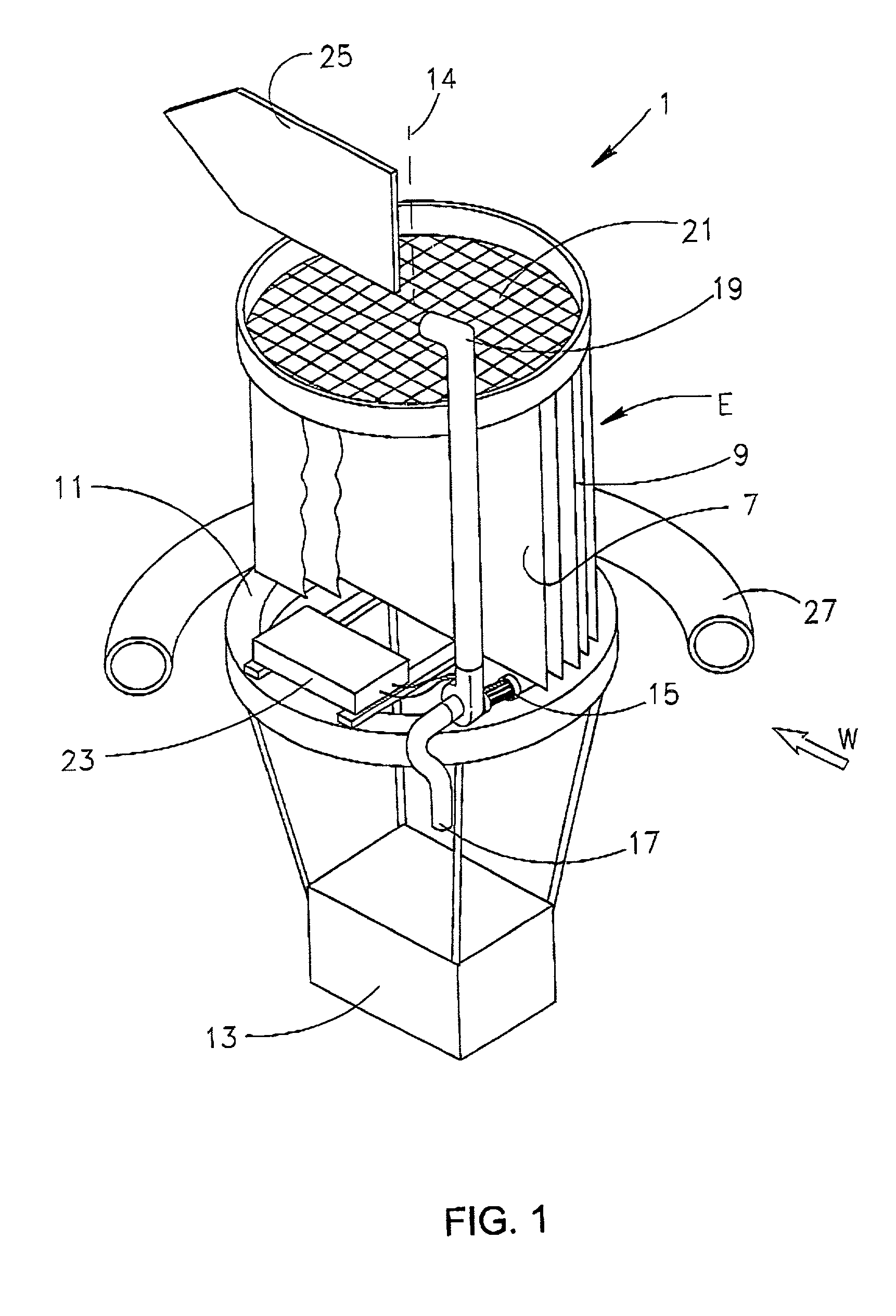
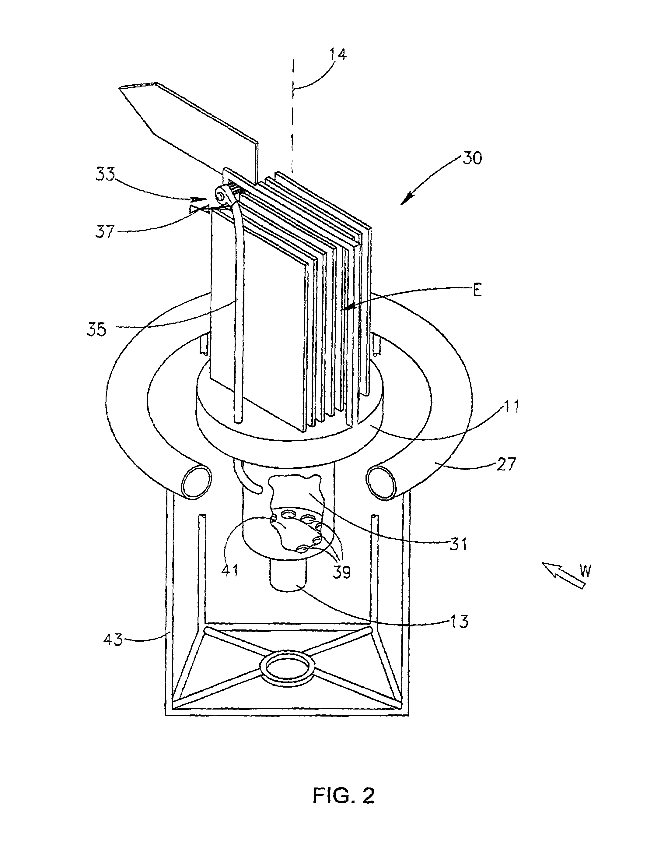
[0033]FIGS. 1, 2, 3, 4 and 5 illustrate different embodiments of an evaporation device designed in accordance with the present invention, to increase the evaporation from a surface 3 of a liquid pond 5 shown in FIGS. 6A and 6B.

[0034]The evaporation device 1 shown in FIG. 1 has a plurality of evaporation elements E each having two evaporation surfaces 7 made from porous fabric which is stretched over vertical frames 9 in a sail-like manner. The evaporation device 1 is designed so as to enable the support of the evaporation elements E above the pond's surface 3 by means of a float structure 11 which is made from buoyant material. The float structure 11 is provided with a weight 13 which is suspended from it along an imaginary vertical axis 14 of the evaporation device 1 to ensure a low centre of gravity for the device 1 thereby keeping it upright on the pond's surface 3.

[0035]The evaporation device 1 has a wetting arrangement comprising a pump 15 having an inlet pipe 17 to the pond 5 ...


PUM

PropertyMeasurementUnit
Shapeaaaaaaaaaa
Areaaaaaaaaaaa
Gravityaaaaaaaaaa

Abstract

An evaporation device for increasing evaporation from a surface of a body of liquid, comprises at least one evaporation element having at least one evaporation surface wettable by the liquid and at least partially exposable to wind when wetted, so as to allow evaporation of the liquid from the evaporation surfaces whereby the total evaporation area of the surface of the body of liquid is increased.

Description

[0001]This application is a continuation in part of PCT / IL00 / 00324 filed Jun. 6, 2000.FIELD OF THE INVENTION[0002]The present invention relates to an evaporation device using wind to increase the rate of evaporation from outdoor ponds.BACKGROUND OF THE INVENTION[0003]Devices of the above kind can be used in outdoor ponds where wastewater is stored and where evaporation is needed to concentrate the waste for further treatment. These ponds present an environmental challenge, as leakage from such ponds can lead to serious groundwater contamination. The requirements of environmental authorities regarding the quality of lining of such ponds are becoming more stringent and therefore the costs thereof tend to increase. For these reasons, there exists a need to reduce the number and size of such evaporation ponds by increasing the rate of evaporation therefrom.[0004]Increasing the evaporation from ponds is also advantageous in the production of solid products like salts and minerals.[0005]K...

Claims


Application Information

Patent Timeline
IPC IPC(8): B01D1/16B01D1/22F26B3/12B01D3/34C02F1/04
CPCB01D1/228C02F1/047B01D3/346Y10S159/28Y02W10/37Y02A20/141
Inventor KEDEM, AVRAHAMGILRON, JACKKEDEM, ORA
Owner B G NEGEV TECH & APPL LTD
Why Eureka
Try Eureka