
Time correction system, time correction instruction device, pointer type timepiece, and time correction method

a time correction and instruction device technology, applied in the field of time correction systems, can solve the problems of large time required for date, large adjustment procedure, and troublesome adjustment procedures, and achieve the effect of minimizing the increase in size and cost of a timepiece and simple procedur

Inactive Publication Date: 2007-01-23
SEIKO EPSON CORP
View PDF17 Cites 56 Cited by
  • Summary
  • Abstract
  • Description
  • Claims
  • Application Information

AI Technical Summary

Benefits of technology

The present invention provides a time correction system that can correct time with a simple procedure without adding external buttons or increasing the size and cost of a timepiece. The system includes a pointer type timepiece and a time correction instruction device. The pointer type timepiece has a pointer, communication section, drive control section, and correction section. The communication section receives time adjustment data and outputs it to the pointer type timepiece. The time correction instruction device has a timing section, time input section, and communication section. The timing section keeps time as reference time data, the time input section inputs the pointed time data, and the communication section outputs the time adjustment data. The system also includes a comparison section that compares the reference time data and the pointed time data. This invention simplifies the process of correcting time and reduces the size and cost of a timepiece.

Problems solved by technology

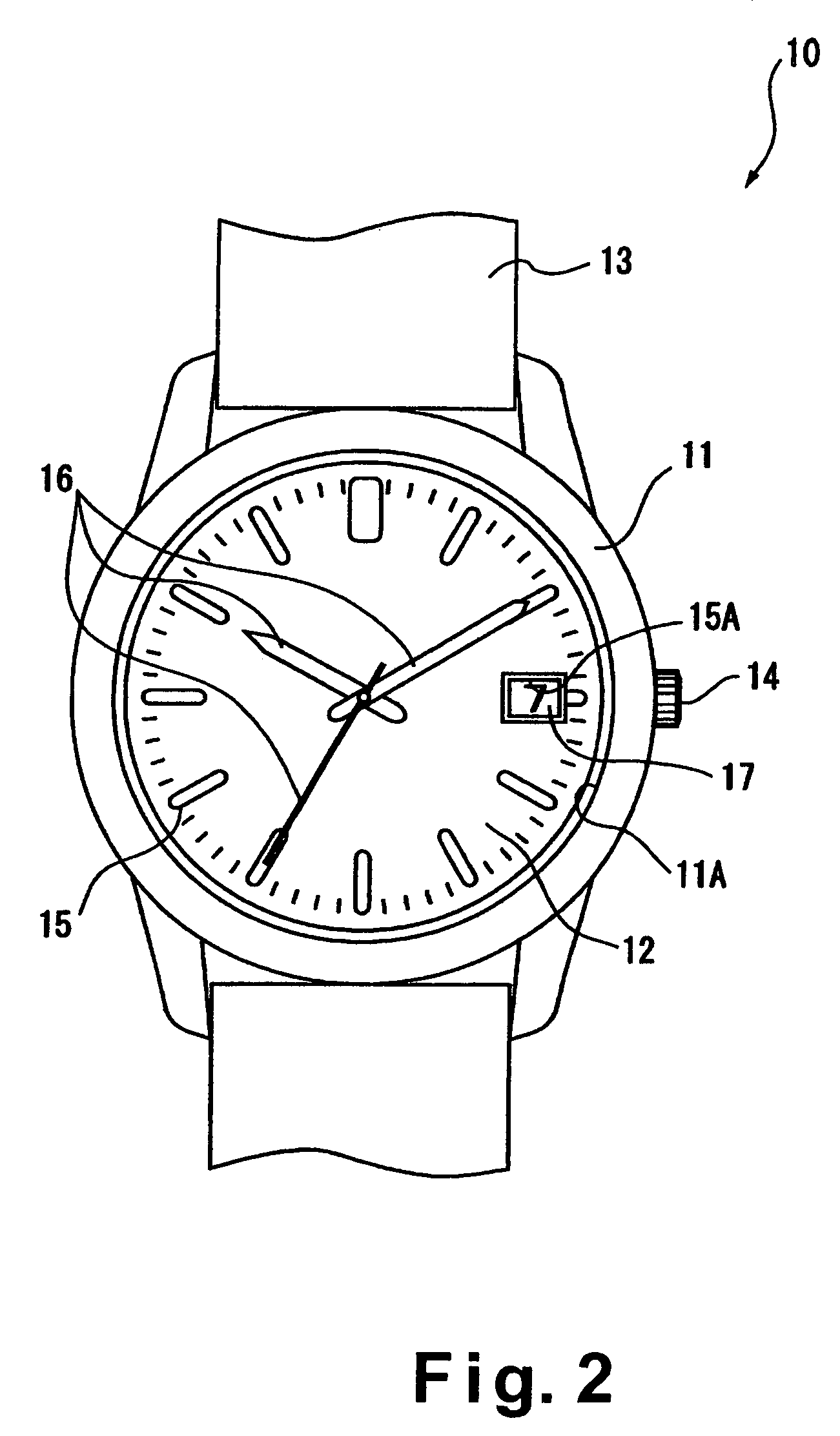
However, such adjustment procedures have been troublesome because winders, buttons, or the like, which are relatively small elements, must be used, and the adjustment procedures have been extremely complicated.
Therefore, when a plurality of timepieces needing battery replacements are brought in, much time is required for date and time adjustment procedures accompanying battery replacements, and the timepieces are not returned to the user on time.
With a timepiece equipped that has an auto-calendar function, as previously described, the year must also be adjusted when replacing the battery, and the mechanism, method, and other adjustment aspects involving winders or buttons has become complicated.
However separate liquid crystal display devices and switches are provided for date correction in this case, so the number of liquid crystal panels, circuits, pressure plates, and other such members increases, which leads to problems related to rising costs of the timepiece, increases in size, and the like.
Also, the back lid must be opened to correct the date even when the counter with the date information is reset by an operation involving static electricity or the like, and the date is corrected for some reason other than battery replacement, which has caused problems of poor operating efficiency.
Furthermore, as shown in Japanese Laid-Open Patent Publication No. 11-190781, a drive device for driving the minute, hour, and second pointers and the date disc is often separately installed in order to provide the auto-calendar function, in which case a switch for detecting the fact that the minute, hour, and second pointers are at 12:00 AM must be provided, which has been disadvantageous in terms of the size of the timepiece, the number of components, the cost of assembly procedures, and the like.
However, this case necessitates space for mounting the configuration unit, which hinders size reduction of the timepiece.
Although the possibility of reducing the size of the configuration unit has also been considered, this approach would be inconvenient in that setting would become more difficult to accomplish.
Furthermore, the setting method itself is not necessarily simple, so the manual needs to be consulted, which may lead to a more complex procedure.
A configuration wherein specific buttons for correcting the date are provided separately to exterior parts has also been considered, but problems of increased cost due to the increase in the number of elements have occurred in this case, and problems of damaging the appearance have occurred particularly in the case of wristwatches and other design-oriented products.

Method used


Image

  • Time correction system, time correction instruction device, pointer type timepiece, and time correction method
  • Time correction system, time correction instruction device, pointer type timepiece, and time correction method
  • Time correction system, time correction instruction device, pointer type timepiece, and time correction method

Examples


second embodiment

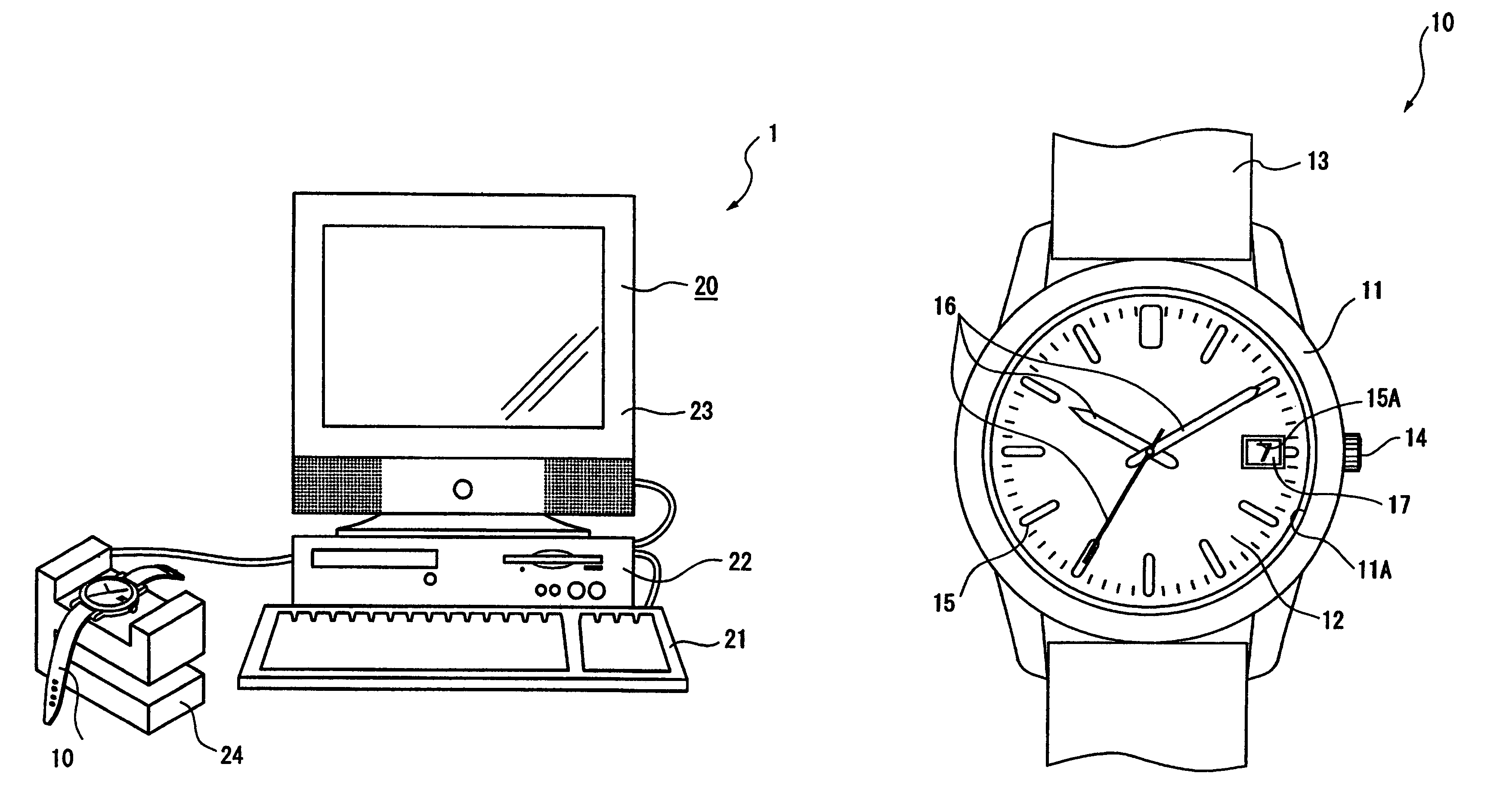
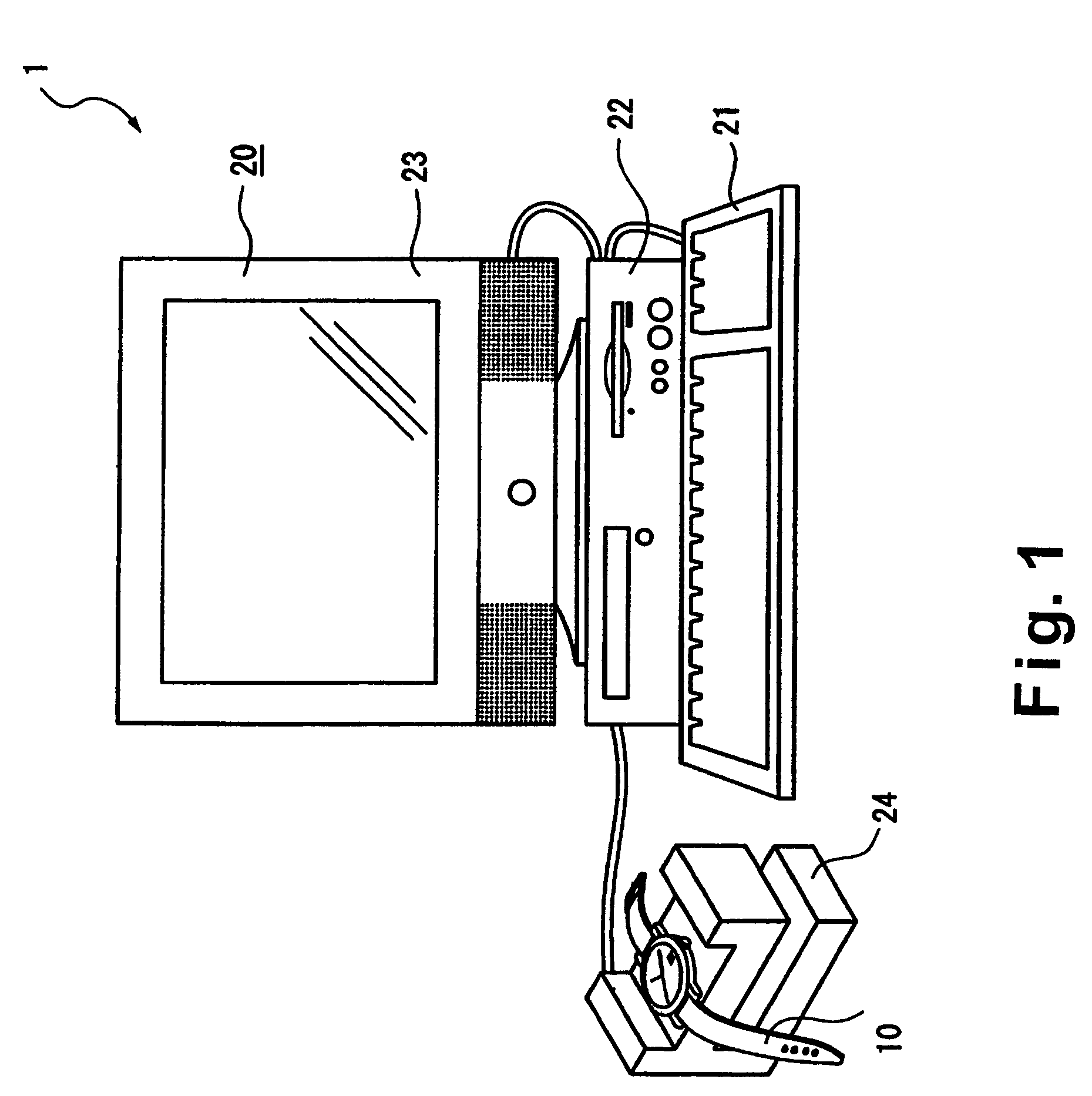
[0079]Referring now toFIGS. 8 through 11, a second embodiment will now be explained. In view of the similarity between the first and second embodiments, the parts of the second embodiment that are identical to the parts of the first embodiment will be given the same reference numerals as the parts of the first embodiment. Moreover, the descriptions of the parts of the second embodiment that are identical to the parts of the first embodiment may be omitted for the sake of brevity. The date / time correction system 2 in accordance with the second embodiment has a substantially similar external appearance as the date / time correction system 1 of the first embodiment shown in FIG. 1, but the internal configuration of the components is different.

[0080]The date / time correction system 2 has a pointer type timepiece 50 with a date display function, and a correction instruction device 60 as a time correction instruction device for correcting the time and date (date / time) displayed by the timepi...


PUM


Abstract

A time correction system has a timepiece with pointers for displaying the time, and a correction instruction device. The correction instruction device has a timing section for timing reference time data, a time input section for inputting pointed time data corresponding to the time indicated by the pointers, a comparison section for comparing the reference time data and the pointed time data, and a communication section for outputting a correction instruction signal based on the results of this comparison to the pointer type timepiece. The pointer type timepiece has an external signal detection circuit for receiving the correction instruction signal, a drive control section for controlling the driving of the pointers, and a time correction control circuit for matching the readings of the pointers with the reference time data based on the received correction instruction signal.

Description

BACKGROUND OF THE INVENTION[0001]1. Field of the Invention[0002]The present invention relates to a time correction system, a time correction instruction device, a pointer type timepiece, and a time correction method. More specifically, the present invention relates to a time correction system, a time correction instruction device, a pointer type timepiece, and a time correction method configured such that the pointer type timepiece and the time correction instruction device are in a communicable state, and the instructed time is automatically corrected in the pointer type timepiece.[0003]2. Background Information[0004]Date-displaying pointer type timepieces that display the time by the positions of rotating pointers and also display the date by a rotating date disc with numerals or the like on the date disc are known in conventional practice. A silver battery or another such primary battery is provided in a date-displaying pointer type timepiece to drive the timepiece itself. Theref...

Claims


Application Information

Patent Timeline
Patent Type & Authority Patents(United States)
IPC IPC(8): G04C11/00G04B19/04G06F1/04G04G5/00G04R20/00
CPCG04C9/02G04R20/00G04G5/002G04R20/28G04R60/14
Inventor AKAHANE, HIDEHIROTAKAHASHI, OSAMU
Owner SEIKO EPSON CORP
Learn More