Multimode speech coding apparatus and decoding apparatus
a speech coding and multi-mode technology, applied in the field of lowbitrate speech coding apparatus, can solve the problem of difficult to encode all input signals with high quality, and achieve the effect of improving coding/decoding performan
- Summary
- Abstract
- Description
- Claims
- Application Information
AI Technical Summary
Benefits of technology
Problems solved by technology
Method used
Image
Examples
first embodiment
[0029](First Embodiment)
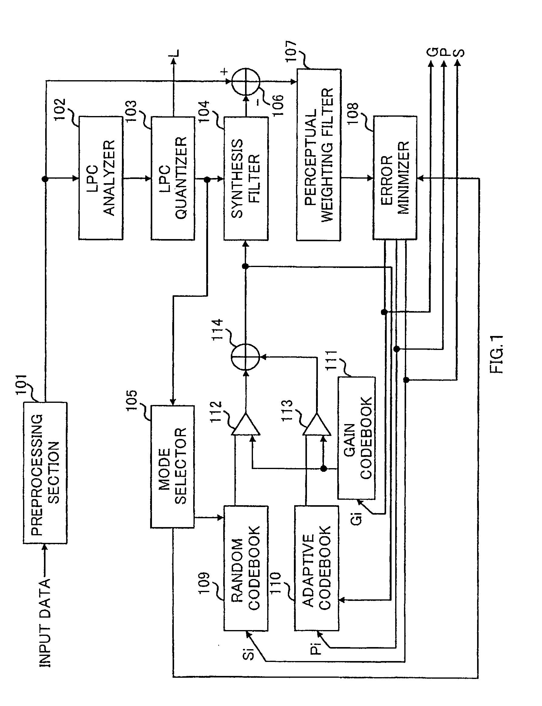
[0030]FIG. 1 is a block diagram illustrating a configuration of a speech coding apparatus according to the first embodiment of the present invention. Input data comprised of, for example, digital speech signals is input to preprocessing section 101. Preprocessing section 101 performs processing such as cutting of a direct current component or bandwidth limitation of the input data using a high-pass filter and band-pass filter to output to LPC analyzer 102 and adder 106. In addition, although it is possible to perform successive coding processing without performing any processing in preprocessing section 101, the coding performance is improved by performing the above-mentioned processing. Further as the preprocessing, other processing is also effective for transforming into a waveform facilitating coding with no deterioration of subjective quality, such as, for example, operation of pitch period and interpolation processing of pitch waveforms.
[0031]LPC analyze...
second embodiment
[0063](Second Embodiment)
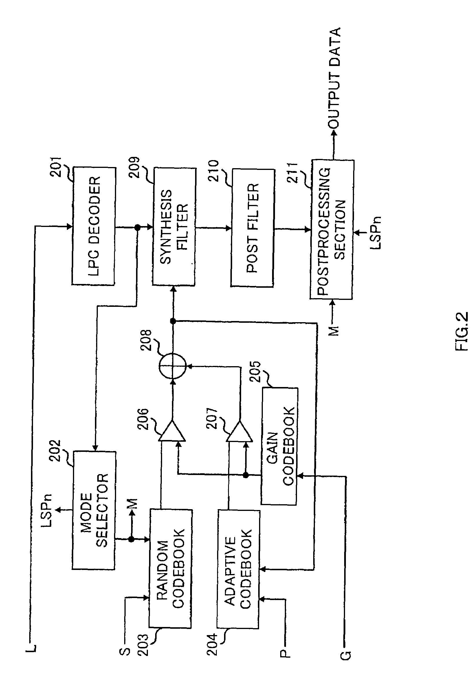
[0064]FIG. 2 shows a configuration of a speech decoding apparatus according to the second embodiment of the present invention.
[0065]The code L representing quantized LPC, code S representing a random code vector, code P representing an adaptive code vector, and code G representing gain information, each transmitted from a coder, are respectively input to LPC decoder 201, random codebook 203, adaptive codebook 204 and gain codebook 205.
[0066]LPC decoder 201 decodes the quantized LPC from the code L to output to mode selector 202 and synthesis filter 209.
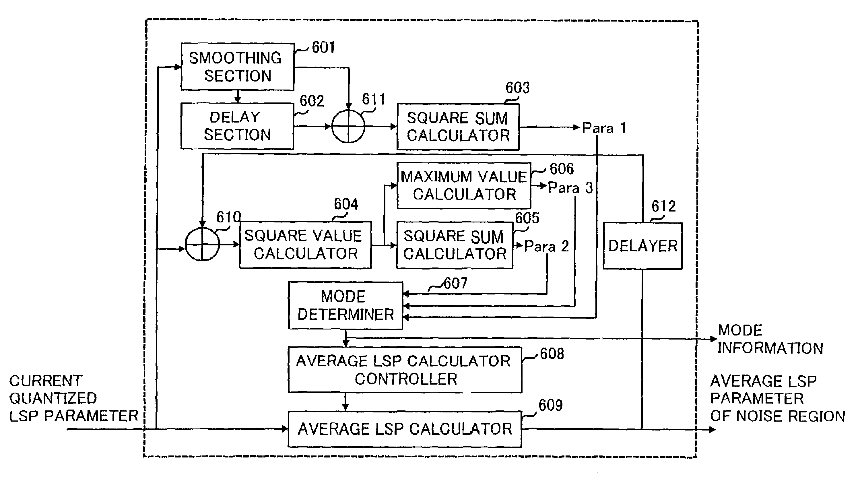
[0067]Mode selector 202 determines a mode for random codebook 203 and postprocessing section 211 using the quantized LPC input from LPC decoder 201, and outputs mode information M to random codebook 203 and postprocessing section 211. Further, mode selector 202 obtains average LSP (LSPn) of a stationary noise region using the quantized LSP parameter output from LPC decoder 201, and outputs LSPn to postprocessi...
third embodiment
[0092](Third Embodiment)
[0093]FIG. 5 is a block diagram illustrating a speech signal transmission apparatus and reception apparatus respectively provided with the speech coding apparatus of the first embodiment and speech decoding apparatus of the second embodiment. FIG. 5A illustrates the transmission apparatus, and FIG. 5B illustrates the reception apparatus.
[0094]In the speech signal transmission apparatus in FIG. 5A, speech input apparatus 501 converts a speech into an electric analog signal to output to A / D converter 502. A / D converter 502 converts the analog speech signal into a digital speech signal to output to speech coder 503. Speech coder 503 performs speech coding processing on the input signal, and outputs coded information to RF modulator 504. RF modulator 504 performs modulation, amplification and code spreading on the coded speech signal information to transmit as a radio signal, and outputs the resultant signal to transmission antenna 505. Finally, the radio signal ...
PUM
 Abstract
Description
Claims
Application Information
 - R&D
- Intellectual Property
- Life Sciences
- Materials
- Tech Scout
- Unparalleled Data Quality
- Higher Quality Content
- 60% Fewer Hallucinations
Browse by: Latest US Patents, China's latest patents, Technical Efficacy Thesaurus, Application Domain, Technology Topic, Popular Technical Reports.
© 2025 PatSnap. All rights reserved.Legal|Privacy policy|Modern Slavery Act Transparency Statement|Sitemap|About US| Contact US: help@patsnap.com


