Shoes sole structures

a technology of sole structure and shoe sole, which is applied in the direction of footwear, clothing, applications, etc., to achieve the effect of reducing the density of shoe soles and reducing the risk of injury

Inactive Publication Date: 2007-01-30
ANATOMIC RES
View PDF351 Cites 65 Cited by
  • Summary
  • Abstract
  • Description
  • Claims
  • Application Information

AI Technical Summary

Benefits of technology

[0051]In a preferred embodiment of the '478 invention, such variations are consistent through all frontal plane cross sections so that there are proportionally equal increases to the theoretically ideal stability plane from front to back. In alternative embodiments, the thickness may increase, then decrease at respective adjacent locations, or vary in other thickness sequences. The thick...

Problems solved by technology

A small number of both street and athletic shoe soles that are commercially available are naturally contoured to a limited extent in that only their bottom soles, which are about one quarter to one third of the total thickness of the entire shoe sole, are wrapped up aro...

Method used


Image

  • Shoes sole structures
  • Shoes sole structures
  • Shoes sole structures

Examples


Embodiment Construction

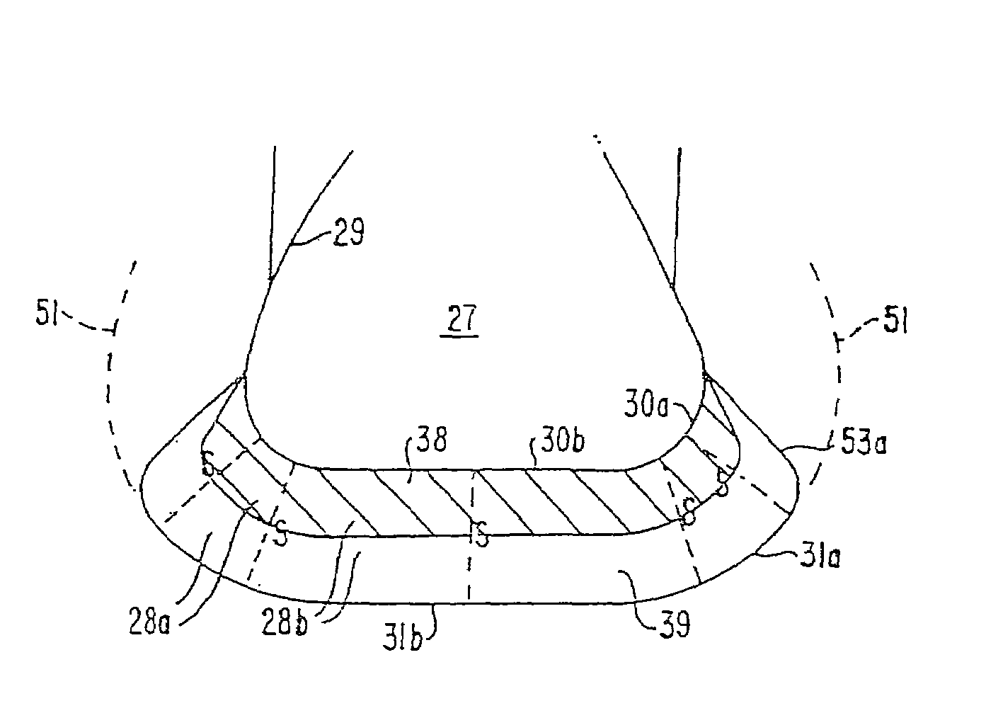
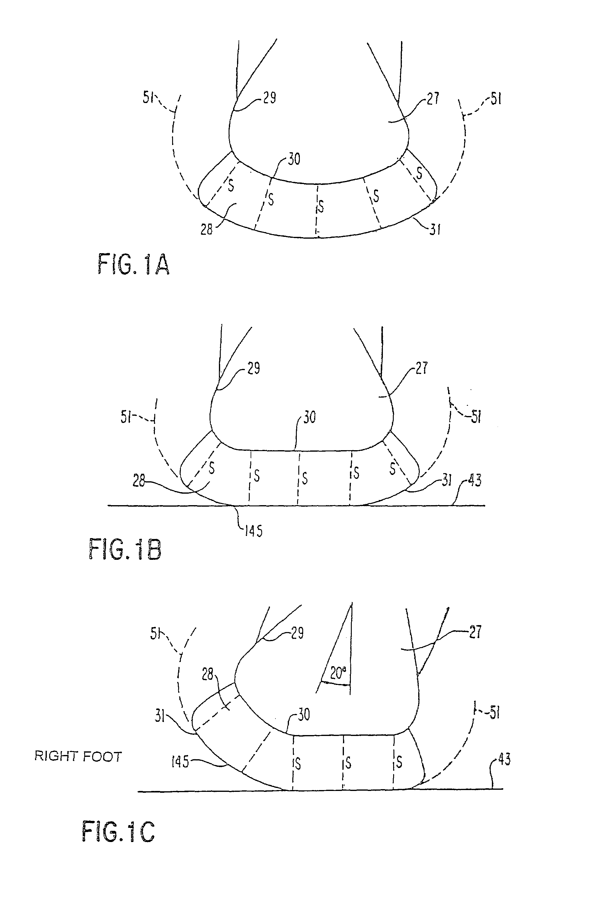
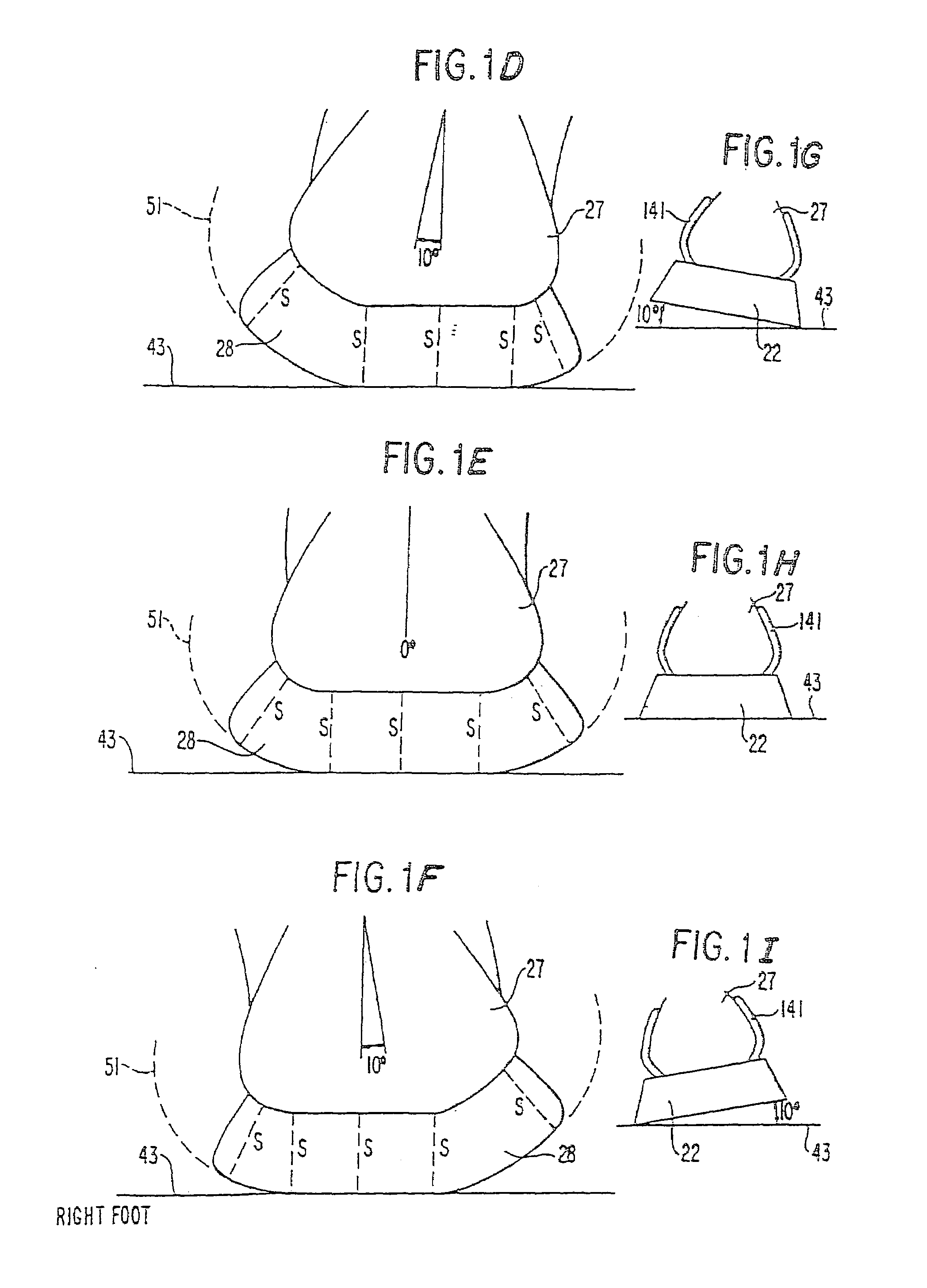
[0101]FIGS. 1A–C illustrate, in frontal or transverse plane cross sections in the heel area, the applicant's concept of the theoretically ideal stability plane applied to shoe soles.

[0102]FIGS. 1A–1C illustrate clearly the principle of natural deformation as it applies to the applicant's design, even though design diagrams like those preceding (and in his previous applications already referenced) are normally shown in an ideal state, without any functional deformation, obviously to show their exact shape for proper construction. That natural structural shape, with its contour paralleling the foot, enables the shoe sole to deform naturally like the foot. In the applicant's invention, the natural deformation feature creates such an important functional advantage it will be illustrated and discussed here fully. Note in the figures that even when the shoe sole shale is deformed, the constant shoe sole thickness in the frontal plane feature of the invention is maintained.

[0103]FIG. 1A is...


PUM


Abstract

In its simplest conceptual form, the applicant's invention is the structure of a conventional shoe sole that has been modified by having its sides bent up so that their inner surface conforms to a shape nearly identical but slightly smaller than the shape of the outer surface of the sides of the foot sole of the wearer (instead of the shoe sole sides conforming to the ground by paralleling it, as is conventional). The shoe sole sides are sufficiently flexible to bend out easily when the shoes are put on the wearer's feet and therefore the shoe soles gently hold the sides of the wearer's foot sole when on, providing the equivalent of custom fit in a mass-produced shoe sole. This invention can be applied to shoe sole structures based on a theoretically ideal stability plane as a basic concept, especially including structures exceeding that plane. The theoretically ideal stability plane is defined as the plane of the surface of the bottom of the shoe sole, wherein the shoe sole conforms to the natural shape of the wearer's foot sole, particularly its sides, and has a constant thickness in frontal or transverse plane cross sections.

Description

[0001]This application is a divisional of U.S. patent application Ser. No. 09 / 974,786 filed Oct. 12, 2001, now U.S. Pat. No. 6,729,046, which is a divisional of U.S. patent application Ser. No. 09 / 907,598 filed Jul. 19, 2001, now U.S. Pat. No. 6,591,519; which is a divisional of U.S. patent application Ser. No. 09 / 734,905 filed Dec. 13, 2000, now U.S. Pat. No. 6,308,439; which is a continuation of U.S. patent application Ser. No. 08 / 477,954 filed Jun. 7, 1995, now U.S. Pat. No. 6,163,982; which is a continuation-in-part of U.S. patent application Ser. No. 08 / 376,661 filed Jan. 23, 1995, now U.S. Pat. No. 6,810,606; which is a continuation of U.S. patent application Ser. No. 08 / 127,487 filed Sep. 28, 1993, now abandoned; which is a continuation of U.S. patent application Ser. No. 07 / 729,886 filed Jul. 11, 1991, now abandoned; which is a continuation of U.S. patent application Ser. No. 07 / 400,714 filed Aug. 30, 1989, now abandoned.BACKGROUND OF THE INVENTION[0002]This invention relate...

Claims


Application Information

Patent Timeline
IPC IPC(8): A43B13/12A43B13/14A43B13/18A43B13/20
CPCA43B13/143A43B13/145A43B13/20A43B13/148A43B13/18A43B13/146
Inventor ELLIS, III, FRAMPTON E.
Owner ANATOMIC RES
Why Eureka
Try Eureka