
Electrical transmission apparatus through rotating tubular members

a transmission apparatus and rotating technology, applied in the direction of survey, directional drilling, borehole/well accessories, etc., can solve the problems of communication between the rotary steerable system (rss) and the measurement while drilling (mwd) devices and the control sub or the surface, and achieve the effect of improving the accuracy of the measuremen

Inactive Publication Date: 2007-01-30
SCHLUMBERGER TECH CORP
View PDF29 Cites 42 Cited by
  • Summary
  • Abstract
  • Description
  • Claims
  • Application Information

AI Technical Summary

Benefits of technology

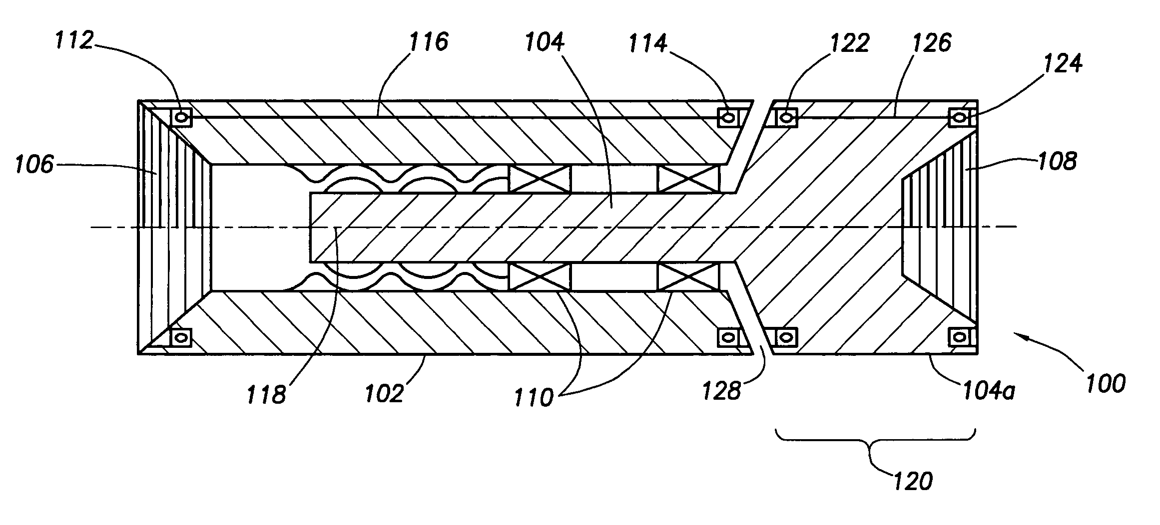
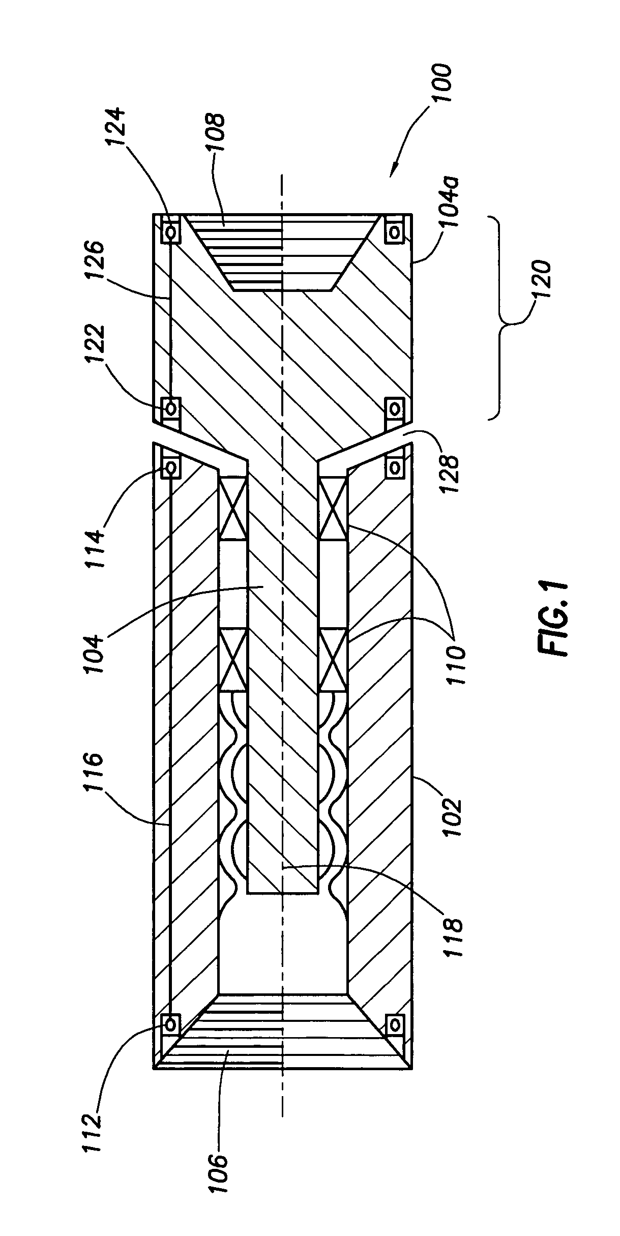
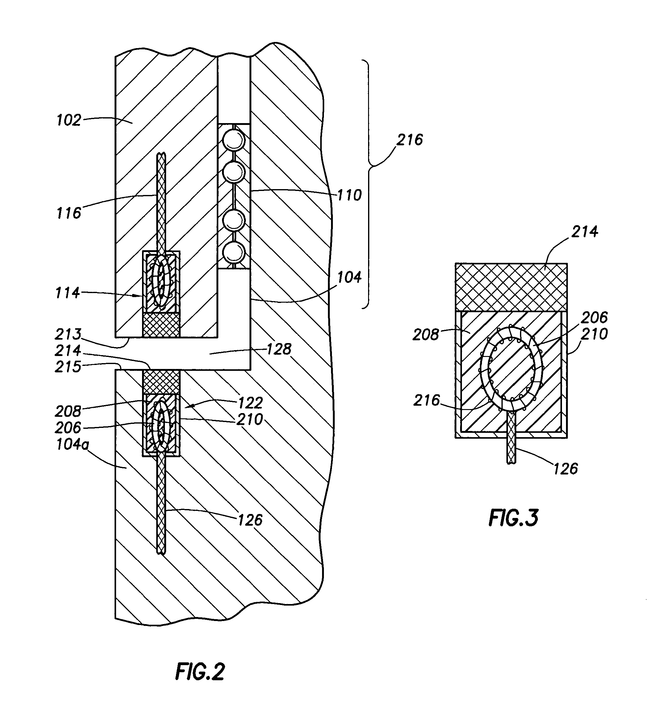
The present invention provides an apparatus and method for transmitting power and data between downhole oilfield tubular members moving at different angular velocities, such as mud motors and devices located downhole or at the control sub or surface. The apparatus includes a first tubular member with a first toroidal inductor and a second end with a second toroidal inductor, and a second tubular member with a first end extending into the longitudinal axial bore of the first tubular member and rotatably supported therein, and a second end with a third toroidal inductor and a fourth toroidal inductor. The first and second tubular members form an axial gap between them, which allows for the transmission of electromagnetic signals. The invention can be used in drill strings to control and track the progress of the bottom hole assembly.

Problems solved by technology

With the use of reamers and underreamers which require rotation of the drillstring with mud motors to drive the drill bit, communication between the rotary steerable system (RSS) and the measurement while drilling (MWD) devices and the control sub or the surface can be problematical.

Method used


Image

  • Electrical transmission apparatus through rotating tubular members
  • Electrical transmission apparatus through rotating tubular members
  • Electrical transmission apparatus through rotating tubular members

Examples


Embodiment Construction

[0027]In the interest of clarity, not all features of actual implementation are described in this specification. It will be appreciated that although the development of any such actual implementation might be complex and time consuming, it would nonetheless be a routine undertaking for those of ordinary skill in the art having the benefit of this disclosure. The present invention provides an apparatus and method for the transfer of power and the communication of signals between the surface and downhole tools in a drill string assembly through the use of inductive couplers.

[0028]In reference to the figures, like numbers have been used for like elements where possible.

[0029]As used herein, the terms “upper” and “lower”, “proximal” and “distal”, and “uphole” and “downhole” and other like terms indicate relative positions above or below a given element on an apparatus. Generally, “proximal” is used to describe the portion of the apparatus uphole and the term “distal” is used to describe...


PUM


Abstract

The present invention provides an apparatus for the communication of power or data signals across the rotating gap of two tubular members, such as the stator and rotor of a mud motor, and between said rotating members of a drill string through inductive couplers located axially along the drill string.

Description

BACKGROUND OF THE INVENTION[0001]The present invention relates generally to downhole tools for use in oilfield drilling operations. More particularly, the present invention relates to the transmission of power and / or data between downhole tools in a drill string and a downhole control sub (or, alternatively, the surface) through coupled inductors located on the longitudinal ends or shoulders of rotating tubular members, such as on the ends or shoulders of a mud motor.[0002]As is well known in the industry, hydrocarbons are recovered from underground reservoirs, by drilling borehole or wellbore with a rotating drill bit attached to the bottom of a drilling assembly. The drilling assembly is attached to the bottom of a tubing member, which can be either rigid or flexible. The apparatus comprising the tubing is commonly referred to as the “drill string” consists of a long string of sections of drill pipe that are connected together end-to-end through threaded pipe connections. When a j...

Claims


Application Information

Patent Timeline
Patent Type & Authority Patents(United States)
IPC IPC(8): E21B4/02H04B10/22E21BE21B7/06E21B17/02
CPCE21B7/068E21B47/122E21B17/028E21B47/13E21B17/0283E21B4/02E21B17/03
Inventor BOYLE, BRUCE WILLIAMDOWNTON, GEOFF
Owner SCHLUMBERGER TECH CORP
Learn More