Rotor brake as well as rotor and rotary-wing aircraft with such a rotor brake

a technology of rotor brake and rotor rotor, which is applied in the direction of mechanical equipment, machines/engines, transportation and packaging, etc., can solve the problems of strong brakes, only relatively slow reduction, and substantial weight of rotor brakes

Inactive Publication Date: 2007-01-30
AIRBUS HELICOPTERS DEUT GMBH
View PDF7 Cites 17 Cited by
  • Summary
  • Abstract
  • Description
  • Claims
  • Application Information

AI Technical Summary

Benefits of technology

[0009]An object of the present invention is to provide a rotor brake that avoids the drawbacks inherent in the state of the art to the greatest extent possible and that effectively prevents an operating error or a malfunction. Moreover, a rotor and a rotary-wing aircraft with such a rotor brake are to be proposed.
[0012]The rotor speed-controlled, centrifugal force-actuated rotor brake deactivation device provides a relatively simple and effective safety system with which the rotor brake can be deactivated or blocked as a function of a predetermined speed, for example, above 40% to 50% of the rated rotor speed, so that an undesired or inadvertent actuation of the rotor brake due to manual operating errors or malfunctions in the brake system itself is ruled out. In this manner, for example, a manual operating error of the rotor brake during flight of a rotary-wing aircraft as well as a malfunction due to a temperature-related increase in the pressure of a rotor brake hydraulic system or else a hydraulic system malfunction can effectively be avoided. Moreover, a failure due to brake actuation at an excessive rotor speed or a structure change of safety-relevant brake components can be prevented. Since the function of a centrifugal force-actuated system is by definition coupled to the speed and can easily be adjusted or linked to certain speeds, the above-mentioned critical speed ranges or speed limits, which have to be observed for rotor brakes, can be especially simply and effectively used as regulation or control parameters for the rotor brake deactivation device. Moreover, the rotor brake according to the present invention, with its rotor speed-controlled, centrifugal force-actuated rotor brake deactivation device, is relatively simple and inexpensive to realize in terms of design and production, also at a low weight, which is especially advantageous for applications in the aviation sector. Consequently, a rotor brake according to the present invention installed in a rotary-wing aircraft such as, for example, a helicopter or a rotary-wing drone contributes to increasing the operational and flight safety of the rotary-wing aircraft.
[0014]The present invention also provides a rotor that includes the rotor brake described herein. This rotor has essentially the same advantages as those already described in conjunction with the rotor brake according to the present invention.

Problems solved by technology

Such a limitation is meaningful since, due to aerodynamic forces, the rotor speed drops relatively quickly to about 40% to 50% of the rated rotor speed, but after that, it decreases only relatively slowly.
Dimensioning rotor brakes that are already effective at 70% to 100% of the rated rotor speed would entail very strong brakes, a substantial weight of the rotor brake as well as increased manufacturing costs.
Therefore, especially in the civilian sector, such a design is neither desired nor, as a rule, necessary.
With conventional rotor brake systems, actuating the rotor brake above a value of 40% to 50% of the rated rotor speed can lead to overheating of the brake disk or of the brake drum since, in this speed range, excessive braking energy is applied to the brake system.
Moreover, an operating error can easily occur with conventional rotor brakes.
For example, it is possible for the pilot to accidentally actuate the rotor brake during flight, which usually has fatal consequences.
Or the rotor brake can be actuated on the ground before the permissible speed of approximately 40% to 50% of the rated rotor speed has been reached which, as already mentioned, might in certain cases cause a failure or a safety-critical change in the brake system.
With hydraulically activated brakes, an erroneous actuation of the braking function can also occur due to a temperature-related increase in the pressure of the hydraulic system or a malfunction of the hydraulic system.
Such an indication, however, does not prevent the rotor brake from being actuated during the flight or above a permissible rotor speed.
This prior art system is relatively complex in terms of design, it is expensive and heavy, which runs counter to the requirements made of lightweight design in aviation technology.

Method used


Image

  • Rotor brake as well as rotor and rotary-wing aircraft with such a rotor brake
  • Rotor brake as well as rotor and rotary-wing aircraft with such a rotor brake
  • Rotor brake as well as rotor and rotary-wing aircraft with such a rotor brake

Examples


Embodiment Construction

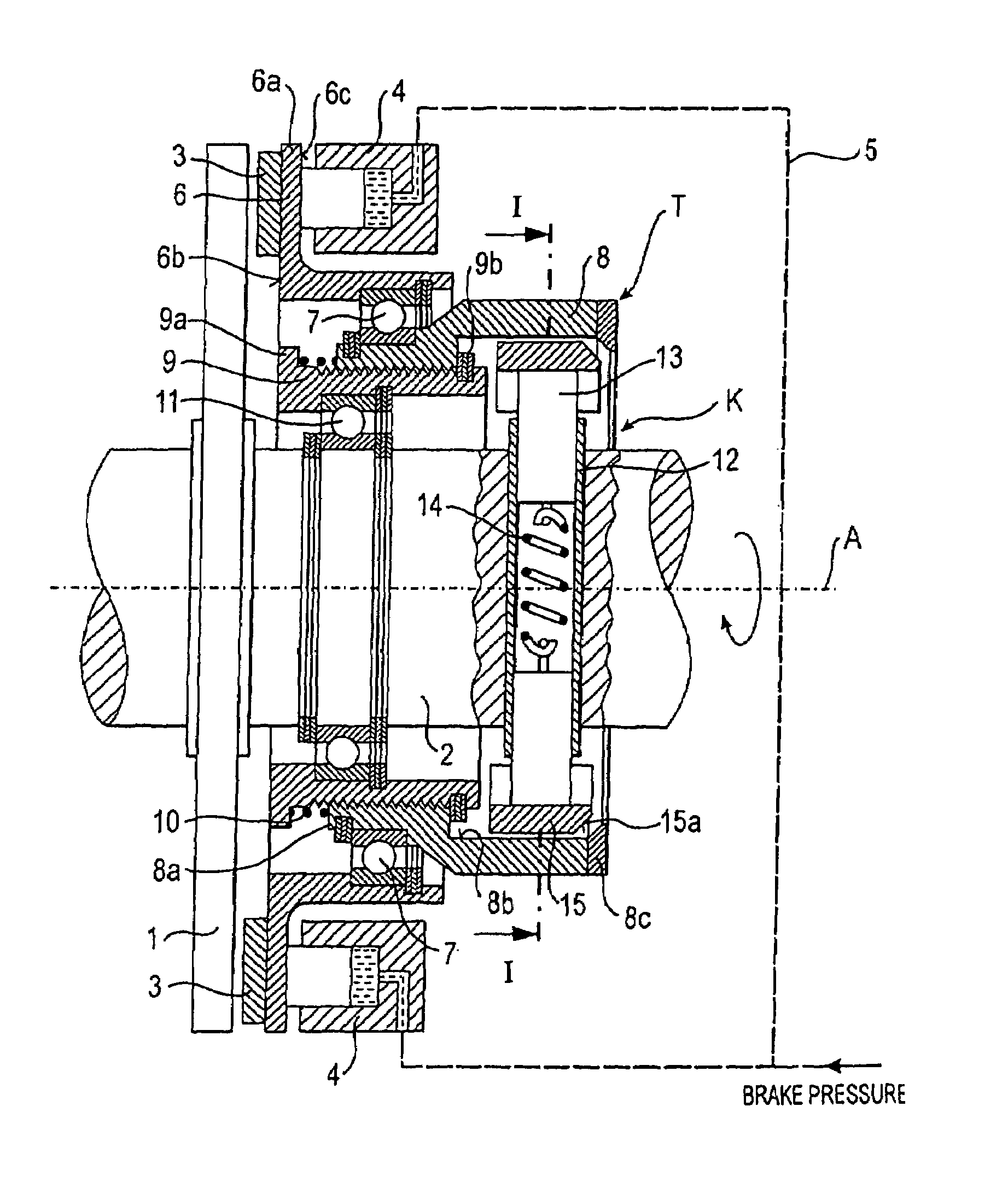
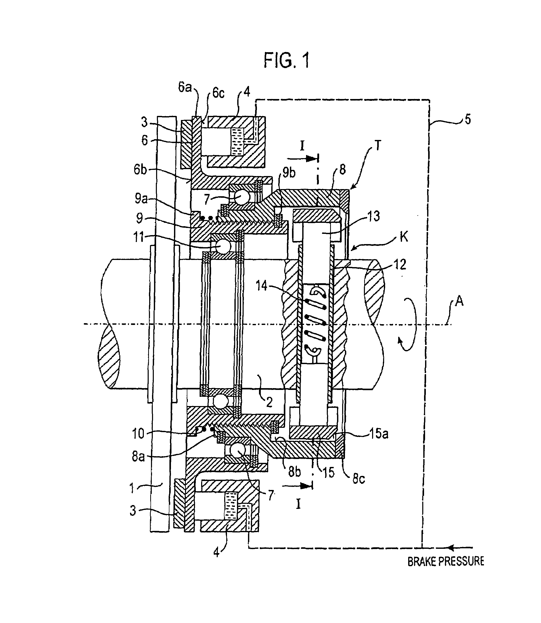
[0019]FIG. 1 schematically shows a longitudinal section through a rotor brake according to the present invention associated with a rotor. In this example, this rotor is a tail rotor of a helicopter that is driven by a tail rotor shaft 2, referred to below for short as the rotor shaft 2. The rotor brake comprises a braking force absorption element in the form of a brake disk 1 that is non-rotatably and axially immovably connected to the rotor shaft 2. However, the brake disk 1 could fundamentally also be attached axially floatingly to the rotor shaft 2. The brake disk 1 extends essentially radially around the rotor shaft 2.

[0020]Moreover, the rotor brake is fitted with several hydraulic brake actuators 4 that are each arranged in a stationary manner, that is to say, for instance, secured to a structural component of a gear housing (not shown), and that serve to actuate a braking force transmission element 3 (here: a brake lining 3). For the sake of simplicity, reference will be made ...


PUM


Abstract

A rotor brake includes a braking force absorption element non-rotatably connected to a rotor shaft; a stationary brake actuator for actuating a braking force transmission element that is functionally coupled to the braking force absorption element so as to exert a braking effect; and at least one rotor speed-controlled, centrifugal force-actuated rotor brake deactivation device. In addition, a rotor having at least one such rotor brake, as well as rotary-wing aircraft, especially a helicopter, having at least one rotor as well as at least one such rotor brake.

Description

[0001]Priority is claimed to German Patent Application No. DE 103 43 055.5, filed on Sep. 16, 2003, the entire disclosure of which is incorporated by reference herein.[0002]The present invention relates to a rotor brake, to a rotor with such a rotor brake as well as to a rotary-wing aircraft, especially a helicopter, with a rotor and with such a rotor brake.BACKGROUND[0003]Rotor brakes are used especially in rotary-wing aircraft such as, for example, helicopters, and in some types of helicopters, they are a safety-relevant system. They serve to brake the rotation of a rotor, especially of a tail rotor, when the rotary-wing aircraft or helicopter is on the ground. Rotor brakes are therefore usually arranged at an outlet of a gear of the rotary-wing aircraft where there is a connection to a tail rotor shaft. As a rule, rotor brakes are configured as disk brakes. The braking force here is exerted using calipers, brake linings or pressure disks by mechanical or hydraulic means. In the c...

Claims


Application Information

Patent Timeline
Patent Type & Authority Patents(United States)
IPC IPC(8): F16D59/00B64C27/02B64C27/14B64C27/32F01D21/00F16D65/14
CPCB64C27/021B64C27/14B64C27/32F01D21/006Y02T50/671F16D2121/02F16D2127/002Y02T50/60
Inventor PODRATZKY, ANDREAS
Owner AIRBUS HELICOPTERS DEUT GMBH
Why Eureka
Try Eureka