End face polishing apparatus

a technology of polishing apparatus and end face, which is applied in the direction of grinding machine components, manufacturing tools, instruments, etc., can solve the problems of variation in polishing angle, radius of curvature and eccentricity, and the polishing length of the rod-shaped member cannot be adjusted, so as to improve the polishing accuracy of the rod-shaped member

Inactive Publication Date: 2007-01-30
SEIKOH GIKEN
View PDF4 Cites 11 Cited by
  • Summary
  • Abstract
  • Description
  • Claims
  • Application Information

AI Technical Summary

Benefits of technology

[0013]In the end face polishing apparatus of the present invention, by providing a slidable contact portion on either the jig plate or the polishing plate to slidably contact the other with a low friction, the jig plate can be maintained horizontal to the polishing plate, thereby improving the polishing accuracy of the rod-shaped member. Further, the length of the rod-shaped members may be made uniform.BRIEF DESCRIPTION OF THE DRAWINGS

Problems solved by technology

If the polished surfaces of the ferrule and the fiber thus polished are not vertical to a center axis of the ferrule, or the polished surfaces have damages, the optical connector having ferrules oppositely connected with each other is deteriorated in accuracy at the opposite position, resulting in an increase in loss.
However, polishing of the rod-shaped member is adjusted by time, so that the polishing length of the rod-shaped member cannot be adjusted.
Therefore, if the ferrules differing in lengths are made to slidably contact the polishing plate, the jig plate tilts to the polishing plate, thereby causing variation in polishing angle, radius of curvature and eccentricity.
Further, there is a problem that variation inferrule lengths occur after polishing.

Method used


Image

  • End face polishing apparatus
  • End face polishing apparatus
  • End face polishing apparatus

Examples


embodiment 1

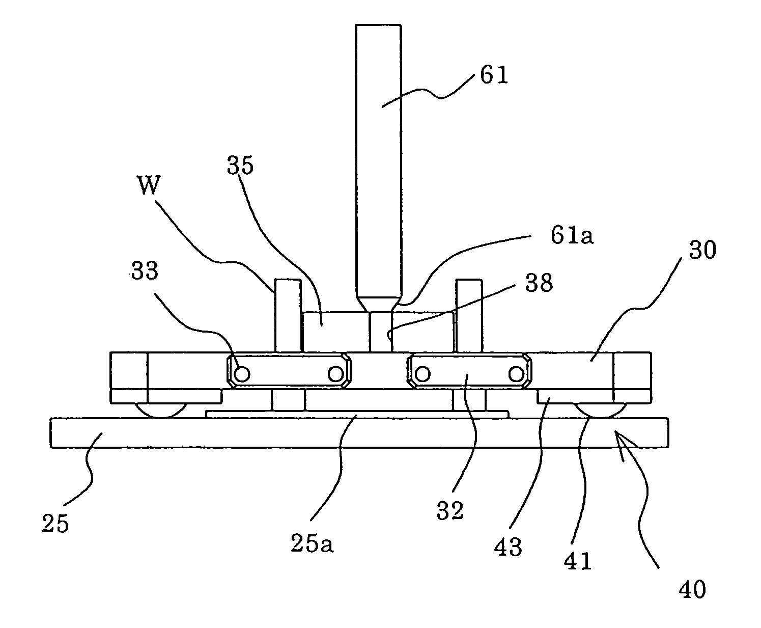
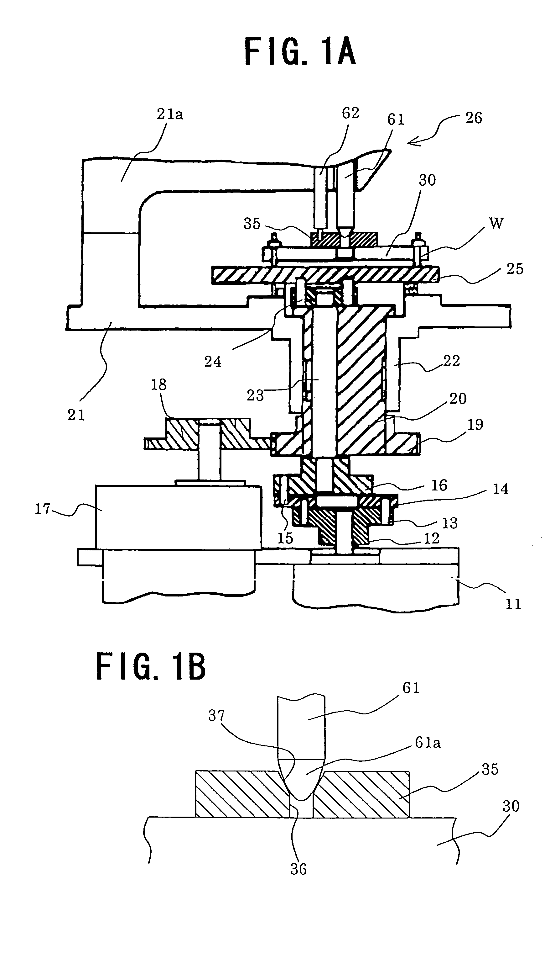
[0021]FIGS. 1A and 1B, respectively, are a part of a perspective view and an enlarged view of an end face polishing apparatus of an embodiment of this invention.

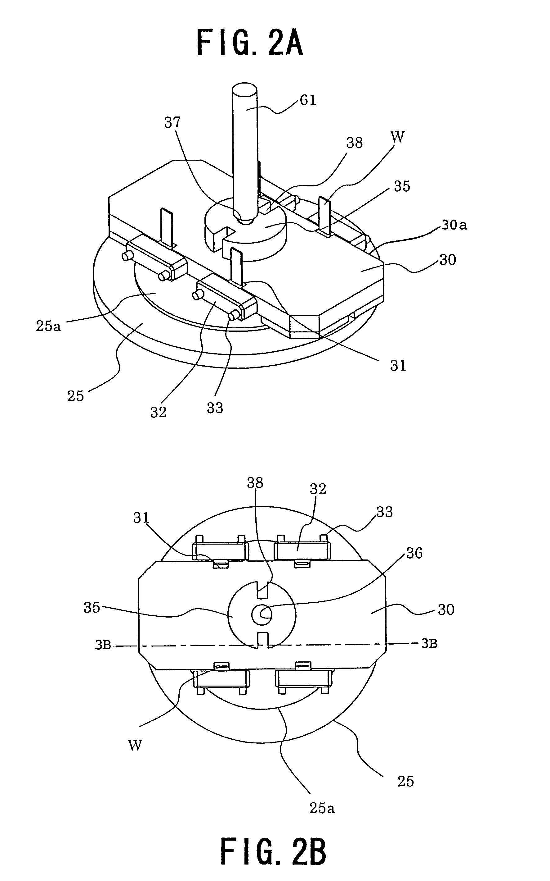
[0022]FIGS. 2A and 2B, respectively, are a perspective view and a top view of a jig plate, and FIGS. 3A and 3B, respectively, are a front view and a cross section view of a jig plate.

[0023]As shown in FIG. 1, the rotating shaft of the motor 11 for self-rotation is firmly fixed to the center portion of the first rotation transmitting shaft 12, and on the first rotation transmitting shaft 12 a plurality of first coupling pins 13 are fixed on the concentric circle with the rotation center as the fulcrum. Then, the respective first coupling pins 13 are coupled rotatably to the eccentric portion of the corresponding respective rotation transmitting plates 14. The eccentric portion of the respective rotation transmitting plates 14 are fixed with second coupling pins 15. The respective second coupling pins 15 are coupled to a secon...

embodiment 2

[0040]In the above Embodiment 1, the ball member 41 which is a slidable contact member 40 is held rotatably in the lower surface of the jig plate, but in Embodiment 2, an example of a ball member provided rotatably on the polishing surface is explained.

[0041]FIGS. 4A and 4B are a perspective view and a cross section view of a jig plate and a polishing plate according to Embodiment 2. Further, members that have similar functions as those in the embodiment described above have the same reference numerals and explanation is omitted.

[0042]As shown in FIGS. 4A and 4B, the slidable contact member 40 in this embodiment has an annular shape, and is structured by a holding portion 45 formed with a groove 46 in the circumferential direction of one end face, and a plurality of spherical shape ball members 41 rotatably held in the groove 46 of the holding portion 45. The slidable contact member 40 is fixed in the region opposing the jig plate 30 in the peripheral portion of the polishing plate ...

embodiment 3

[0044]In the above described Embodiments 1 and 2, the slidable contact member 40 was a ball member 41 so that slidable contact was with low friction, but Embodiment 3 is an example where a metal material is used as a slidable contact member which slidable contacts with low friction.

[0045]FIGS. 5A and 5B are a plan view and a cross section view of a jig plate and a polishing plate according to Embodiment 3. Further, members that have similar functions as those in the embodiment described above have the same reference numerals and explanation is omitted.

[0046]As shown in FIG. 5, the slidable contact member 40 of this embodiment is made of a protruding portion 50 which is a peripheral portion of the polishing plate 25 protruding elongated in the direction of the jig plate 30. The polishing plate 25 provided with an elongated slidable contact member 40 is formed of oil-less metal with low friction resistance at time of slidable contact.

[0047]In this way, by making the slidable contact m...


PUM

PropertyMeasurementUnit
pressureaaaaaaaaaa
lengthaaaaaaaaaa
lengthsaaaaaaaaaa

Abstract

An end face polishing apparatus has a jig plate for supporting at least one workpiece having an end face and a polishing plate mounted for undergoing movement. A polishing member is mounted on the polishing plate for undergoing movement therewith to polish the end face of the workpiece. A slidable contact member is disposed on the jig plate for slidable contact with the polishing plate during a polishing operation to thereby regulate a polishing amount of the end face of the workpiece.

Description

CROSS-REFERENCE TO RELATED APPLICATIONS[0001]The present application is a divisional of U.S. application Ser. No. 09 / 783,878 filed on Feb. 15, 2001 now U.S. Pat. No. 6,800,021 and claiming a priority date of Mar. 13, 2000.BACKGROUND OF THE INVENTION[0002]1. Field of the Invention[0003]The present invention relates to an end face polishing apparatus for polishing end faces of rod-shaped members of optical communication fibers and the like.[0004]2. Description of the Related Art[0005]An optical communication fiber is used after it has been adhered and fixed to a center hole of a ferrule which is a main member of a connector, and then an end face of the ferrule and an end face of a fiber are simultaneously smoothly polished to become a mirror surface. If the polished surfaces of the ferrule and the fiber thus polished are not vertical to a center axis of the ferrule, or the polished surfaces have damages, the optical connector having ferrules oppositely connected with each other is det...

Claims


Application Information

Patent Timeline
Patent Type & Authority Patents(United States)
IPC IPC(8): B24B7/00B24B1/00G02B6/36B24B19/00B24B19/22G02B6/00G02B6/38
CPCG02B6/3863B24B19/226
Inventor MINAMI, KOJITAIRA, JUNJI
Owner SEIKOH GIKEN
Why Eureka
Try Eureka