Methods and instruments for interbody surgical techniques

a technology of interbody surgery and methods, applied in the field of spine surgical techniques and instruments, can solve the problems of disc displacement or damage, nerve damage, pain, muscle weakness, and even paralysis, and achieve the effect of reducing the displacement or damage of the disc, and reducing the height of the disc spa

Inactive Publication Date: 2007-01-30
SDGI HLDG
View PDF34 Cites 29 Cited by
  • Summary
  • Abstract
  • Description
  • Claims
  • Application Information

AI Technical Summary

Problems solved by technology

The discs may be displaced or damaged due to trauma, disease or aging.
A herniated or ruptured annulus fibrosis may result in nerve damage, pain, numbness, muscle weakness, and even paralysis.
Furthermore, as a result of the normal aging processes, discs dehydrate and harden, thereby reducing the disc space height and producing instability of the spine and decreased mobility.
Traditional surgical procedures for correction of spinal defects can cause significant trauma to the nerves and vasculature adjacent the spine.
The potential for tissue trauma can be of particular concern when the surgical procedure dictates the use of a cutting instrument in the disc space in order to remove disc and bone material to prepare the disc space for a fusion device, intervertebral spacer, or other implant.
While reducing the potential for contact with surgical instruments, manipulation and removal of the nerves and vasculature can still result in trauma and an increase the time and difficulty of the surgical procedure.
One disadvantage with the instrumentation disclosed in the '977 patent is that the cutting head is positioned between the spacer and the adjacent nerves and vasculature.
One disadvantage with this technique is that the procedure is performed through a sleeve, thus limiting working space and visibility of the surgeon.
A further disadvantage is that the height of the prepared disc space is limited by the spacing between penetrating portions of the distractor and the inner diameter of the sleeve.

Method used


Image

  • Methods and instruments for interbody surgical techniques
  • Methods and instruments for interbody surgical techniques
  • Methods and instruments for interbody surgical techniques

Examples


Embodiment Construction

[0029]For the purposes of promoting an understanding of the principles of the present invention, reference will now be made to the embodiments illustrated in the drawings, and specific language will be used to describe the same. It will nevertheless be understood that no limitation of the scope of the invention is intended thereby. Any alterations and further modification in the described processes, systems, or devices, and any further applications of the principles of the invention as described herein are contemplated as would normally occur to one skilled in the art to which the invention relates.

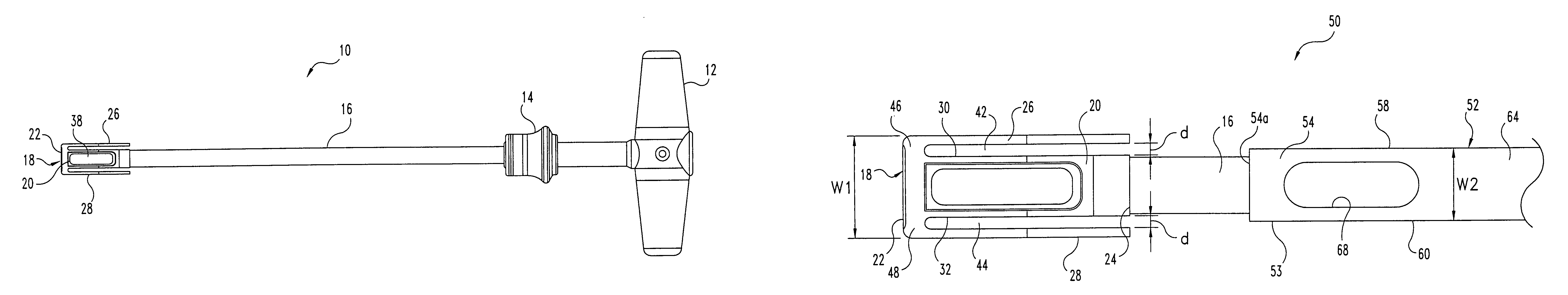
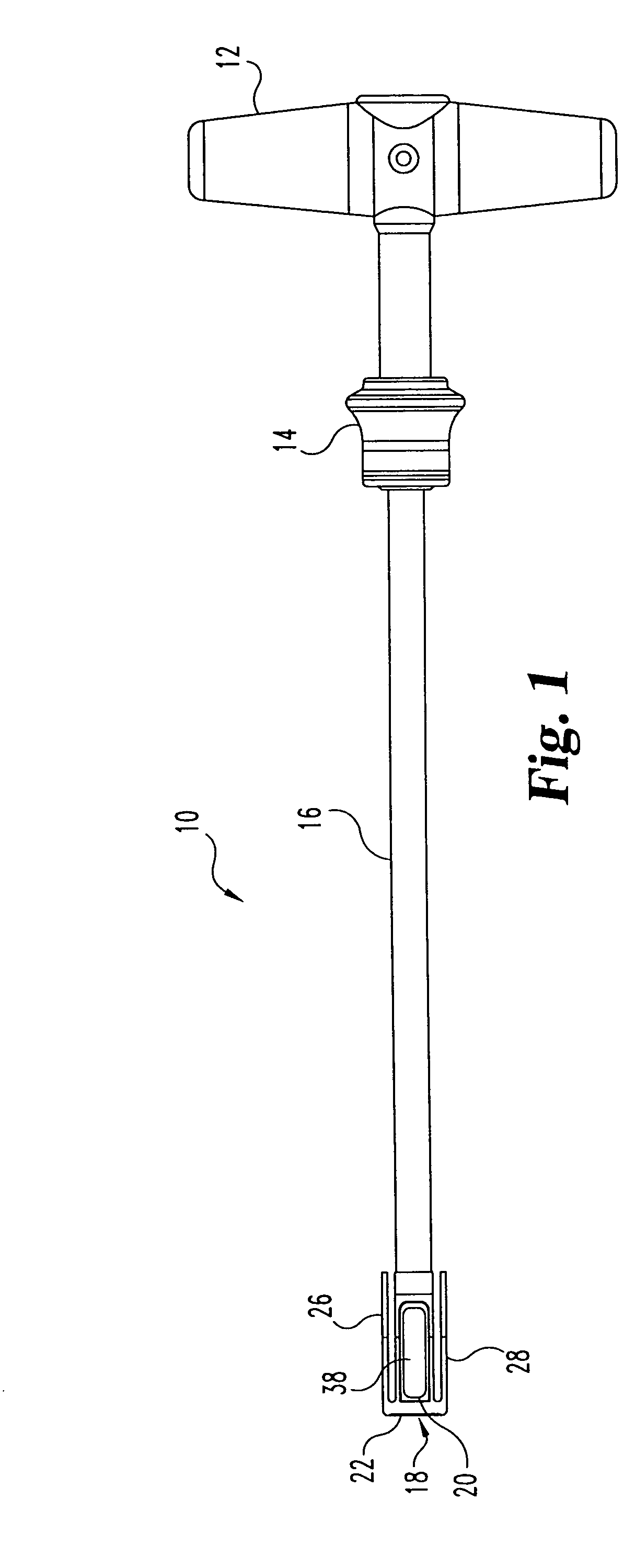
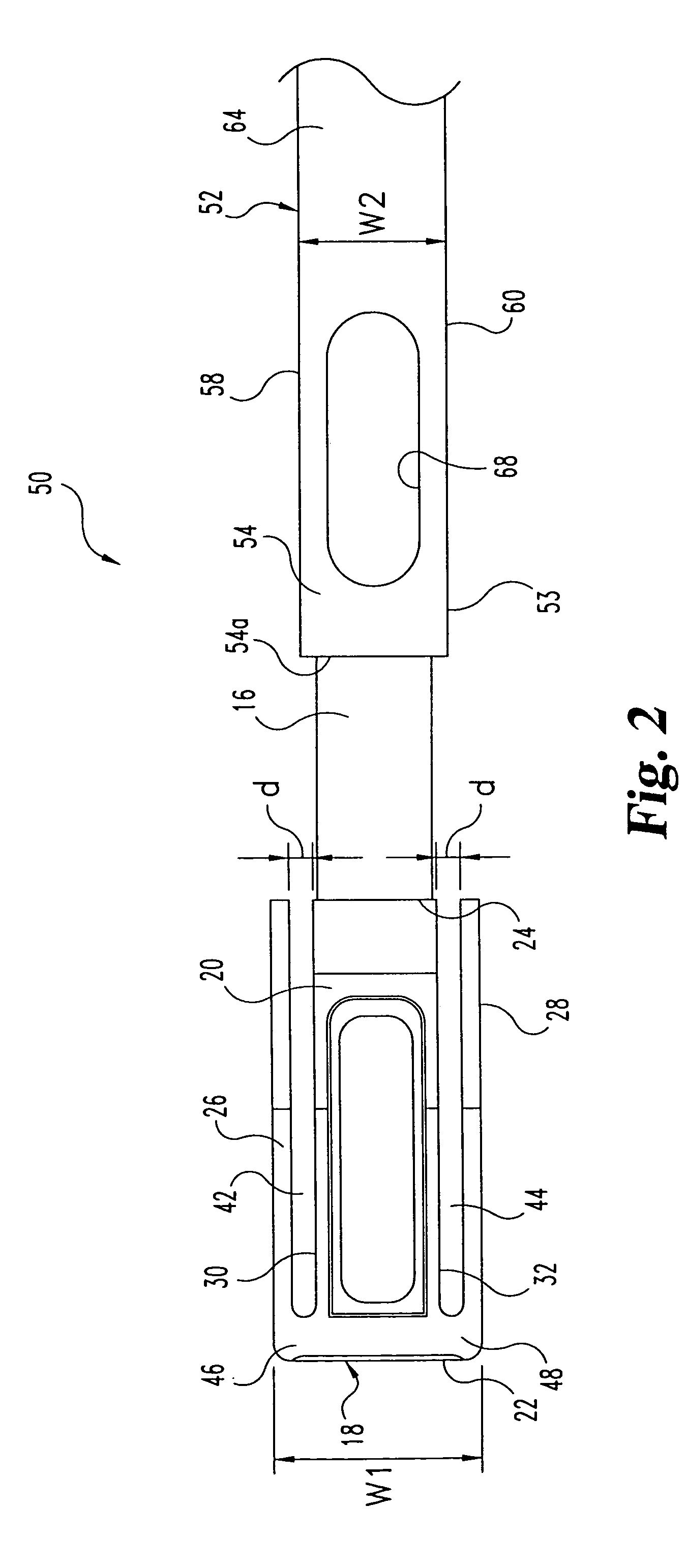
[0030]The instruments and methods of the present invention have application to a wide range of surgical procedures, and particularly spinal procedures for preparing a disc space for insertion of an implant into the disc space. It is further contemplated that the surgical instruments and methods of the present invention have application in open surgical procedures and in minimally invasive...


PUM


Abstract

This invention relates to methods and instruments for performing a surgical procedure in a disc space between adjacent vertebrae. The instruments include a distractor and a cutting instrument. In one embodiment the distractor includes a body portion and a pair of flanges extending along opposite sides of the body portion such that a slot is formed between the flanges and the body portion. The cutting instrument is positionable over the body portion and into the slots of the distractor so that the flanges are positioned between the cutting instrument and the adjacent tissue.

Description

CROSS-REFERENCE TO RELATED APPLICATION[0001]This application is a continuation of U.S. patent application Ser. No. 09 / 692,980, filed Oct. 20, 2000, and issuing as U.S. Pat. No. 6,599,291 which is hereby incorporated by reference in its entirety.FIELD OF THE INVENTION[0002]The present invention relates to spinal surgical techniques and instruments. More particularly, while aspects of the present invention may have other applications, the invention provides instruments and techniques suited for interbody spinal surgery.BACKGROUND OF THE INVENTION[0003]Normally, intervertebral discs, which are located between endplates of adjacent vertebrae, stabilize the spine and distribute forces between the vertebrae and cushion vertebral bodies. The discs may be displaced or damaged due to trauma, disease or aging. A herniated or ruptured annulus fibrosis may result in nerve damage, pain, numbness, muscle weakness, and even paralysis. Furthermore, as a result of the normal aging processes, discs d...

Claims


Application Information

Patent Timeline
Patent Type & Authority Patents(United States)
IPC IPC(8): A61B17/60A61B17/56A61B17/00A61B17/02A61B17/16A61B17/17A61B17/32
CPCA61B17/1671A61B17/320016A61B17/1757A61B17/1604A61B2017/0256A61B2017/00261
Inventor FOLEY, KEVIN T.MOORE, JEFFREY D.ESTES, BRADLEY T.LIU, MINGYANJOSSE, LOIC
Owner SDGI HLDG
Why Eureka
Try Eureka