
Projection type image display apparatus

Inactive Publication Date: 2007-01-30
HITACHI LTD
View PDF9 Cites 10 Cited by
  • Summary
  • Abstract
  • Description
  • Claims
  • Application Information

AI Technical Summary

Benefits of technology

[0005]An embodiment of the present invention provides a new, useful image display technique which minimizes the possibility of color mixing of light rays directed onto the panel and image contrast deterioration and improves the light utilization efficiency.

Problems solved by technology

However, since it requires plural rotary prisms, it cannot be compact.
In addition, it uses not only plural rotary prisms but also many lenses and dichroic mirrors, so it is expensive and its light utilization efficiency is low due to the use of many lenses.
Besides, the rotational positions of plural rotary prisms must be controlled in order to adjust the spots on the panel on which the R, G and B light rays are thrown and this adjustment is troublesome.
Furthermore, in the conventional optical unit, R, G, and B light rays from dichroic mirrors overlap each other on a rotary polyhedron, causing mixing of the colors or contrast deterioration due to stray light.

Method used


Image

  • Projection type image display apparatus
  • Projection type image display apparatus
  • Projection type image display apparatus

Examples


first embodiment

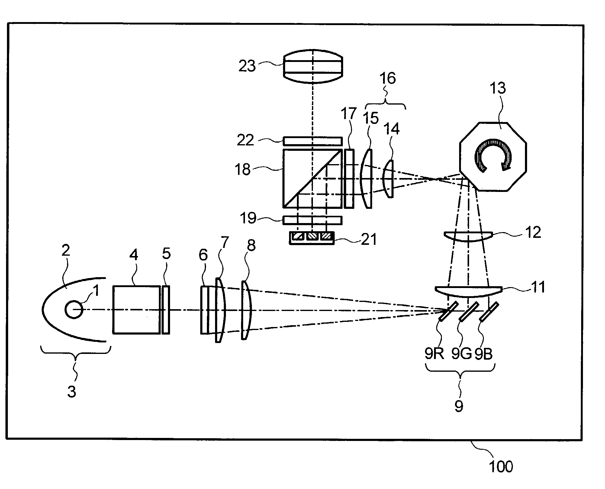
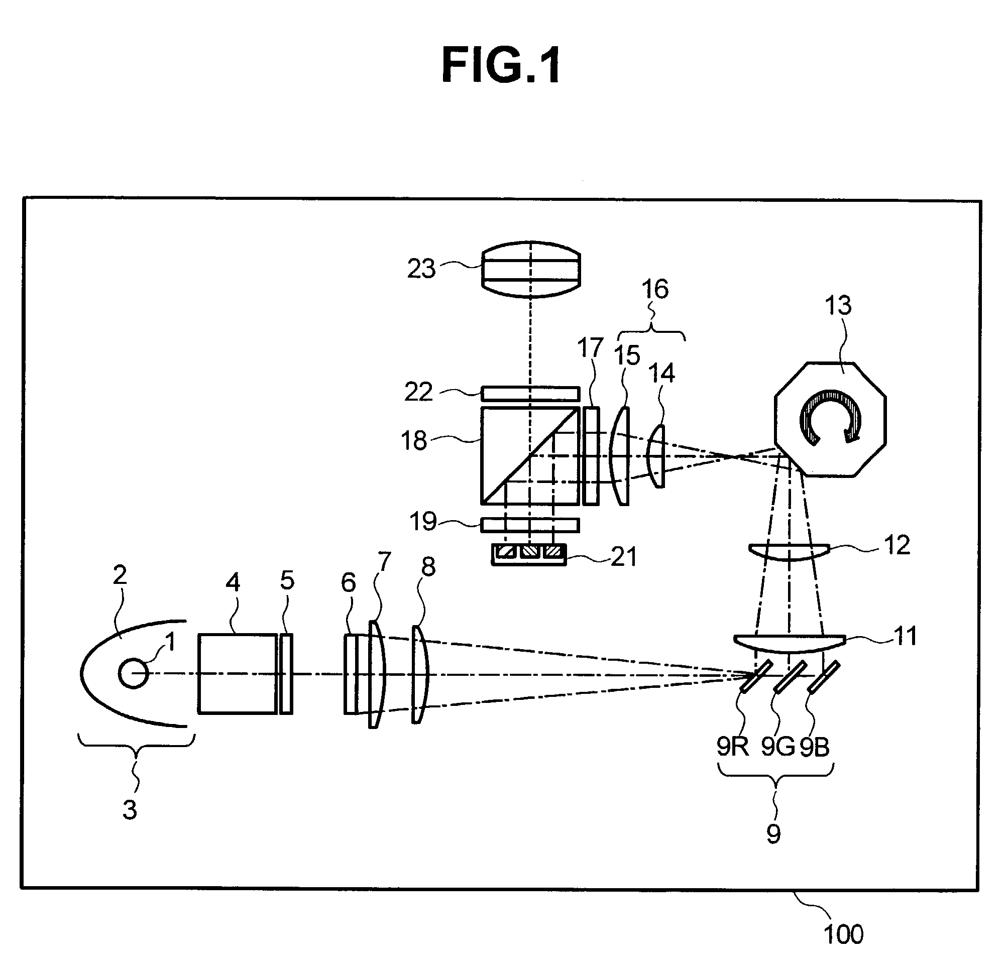
[0025]FIG. 1 shows the general structure of an optical unit included in a display device 100 according to the present invention. The display device 100 is a projection-type television according to one embodiment of the present invention.

[0026]As shown in the figure, light from a lamp unit 3, which is obtained by reflecting light from a lamp (arc) 1 with a reflector 2, passes through a polarizing beam splitter 4 (hereinafter called PBS) to convert the light to either S polarized light or P polarized light, then the polarized light enters a first lens array 5 to form plural secondary lamp images. Then, the light from the first lens array 5 passes through a second lens array 6 which includes a plurality of condenser lenses, lies in the vicinity of the area where plural secondary lamp images are formed, and forms an image of each lens of the first lens array 5 on a liquid crystal panel 21 (hereinafter called the “panel” or “image display device”) which will be mentioned later.

[0027]The ...

second embodiment

[0061]FIG. 6 is a perspective view of an optical unit according to the present invention. The elements equivalent as those shown in FIG. 1 are designated with the same reference numerals and their description is omitted here.

[0062]As shown in the figure, the outer wall of the reflector 2 is partially cut so that a rectangular beam is emitted. Part of the beam which has entered a polarization converter 61 passes through the polarization converter 61 and exits as P polarized light; then, after it is converted into S polarized light by a ½λ plate, it enters the first lens array 5. Other part of the beam is reflected by the first reflective surface 61a of the polarization converter 61, and further reflected by its second reflective surface 61b. It also enters the first lens array 5 as S polarized light. Then the light which has passed through the first and second collimator lenses 7, 8 is separated into R, G, and B light rays by the color separation mirrors 9 and the light rays go to th...

third embodiment

[0064]FIG. 7 is a perspective view of an optical unit according to the present invention. The elements equivalent as those shown in FIG. 1 are designated with the same reference numerals and their description is omitted here. Numeral 79 represents a color separation mirror. The color separation mirror 79 may be prepared as follows: a glass plate assembly, which consists of three glass plates with dichroic mirrors between glass plates and on the outer face of an outer glass plate, is cut into a strip in a way that the incident light side is almost perpendicular to light rays; then it is polished.

[0065]In comparison with the case as shown in FIG. 1 where the dichroic mirror 9R for R light, dichroic mirror 9G for G light, dichroic mirror 9B for B light are provided in the air, the color separation mirror 79 in this embodiment, which is made of glass and dichroic mirrors, is equal in the physical distance between mirrors, but different in the optical length. Let's assume that c represen...


PUM


Abstract

A projection type image display apparatus includes a light source to emit light; a polarizing beam splitter to polarize the light received from the light source; a first lens array including a plurality of first lens cells having rectangular shapes to receive the light from the polarizing beam splitter, each first lens cell having a first side and a second side, the first side being longer than the second side, the first lens array having a rectangular shape, the first lens array having a third side and a fourth side, the third side being longer than the fourth side, the first sides of the first lens cells and the third side of the first lens array extending along a first direction; a second lens array including a plurality of second lens cells and being configured to receive the light from the first lens array, the second lens array having a rectangular shape and having a fifth side and a sixth side, the fifth and sixth sides of the second lens array having substantially the same dimensions as the third and fourth sides of the first lens array; a color separator configured to separate the light from the second lens array into a plurality of light rays of different colors; an image display device configured to form an optical image from the plurality of light rays; and a projector configured to project the plurality of light rays emitted from the image display device as a color image.

Description

CROSS-REFERENCES TO RELATED APPLICATIONS[0001]The present application is related to and claims priority from Japanese Patent Application No. 2002-56868, filed on Mar. 4, 2002.BACKGROUND OF THE INVENTION[0002]A conventional optical unit has been commonly known in which, after light from a lamp passes through a first and a second lens array, a polarizing beam splitter (PBS), and a collimator lens, it is separated into R, B, and G light rays by means of plural dichroic mirrors; then the R, B, G light paths are altered through rotary prisms respectively so that the respective color light rays are directed onto a light valve device (hereinafter simply called “panel”) in different areas and the areas on which color light rays are thrown scroll in a prescribed direction on the panel sequentially.[0003]The above conventional optical unit has an advantage that it uses a single-plate panel and is easy to assemble. However, since it requires plural rotary prisms, it cannot be compact. In addit...

Claims


Application Information

Patent Timeline
IPC IPC(8): H04N5/74G02F1/00G02B26/10G02B3/00G02B26/12G02B27/09G02B27/18G02F1/13357G03B21/00G03B33/12H04N9/31
CPCG02B26/123G02B26/124H04N9/3197H04N9/3117H04N9/315G02B27/0961G03B33/12
Inventor OUCHI, SATOSHIMIYOSHI, TOMOHIROIMAHASE, TAROYATSU, MASAHIKOHIRATA, KOJI
Owner HITACHI LTD
Learn More