
Data transmission

Active Publication Date: 2007-01-30
TEXAS INSTR INC
View PDF7 Cites 6 Cited by
  • Summary
  • Abstract
  • Description
  • Claims
  • Application Information

AI Technical Summary

Problems solved by technology

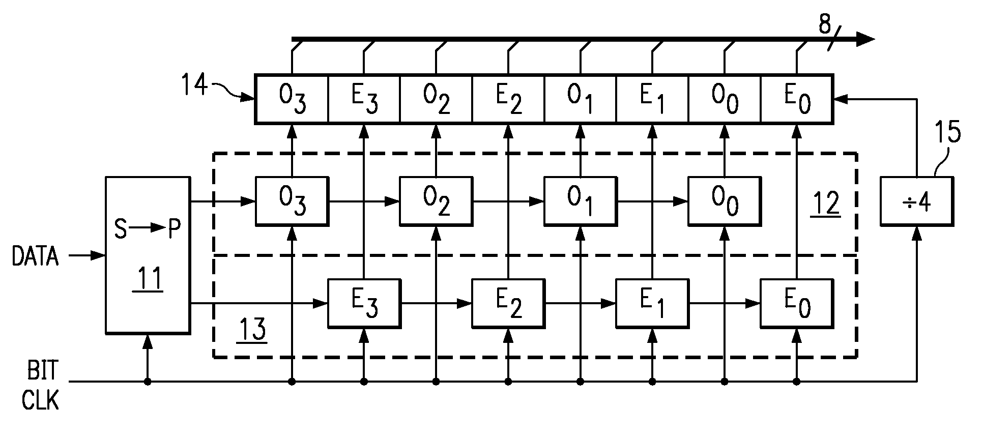
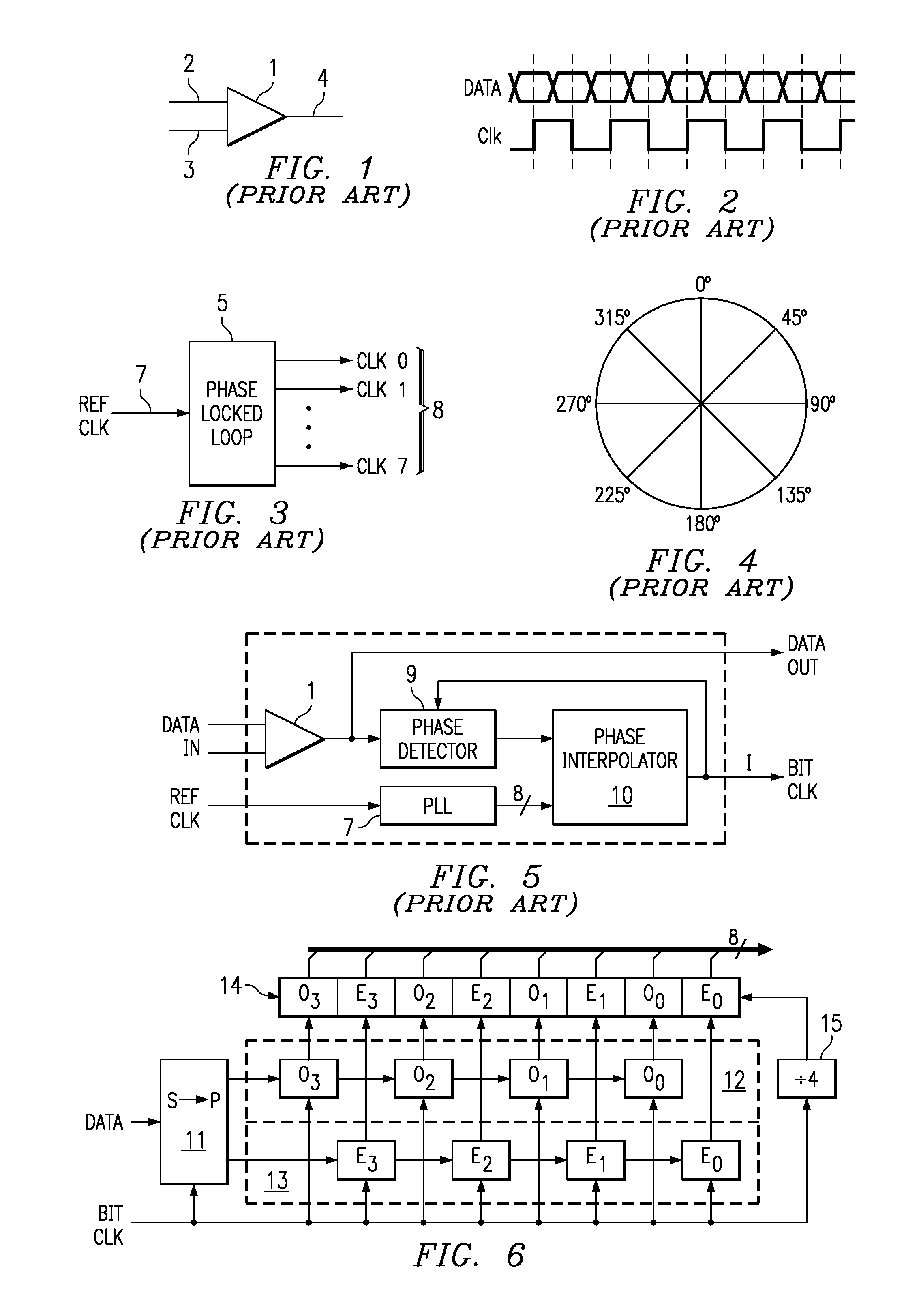
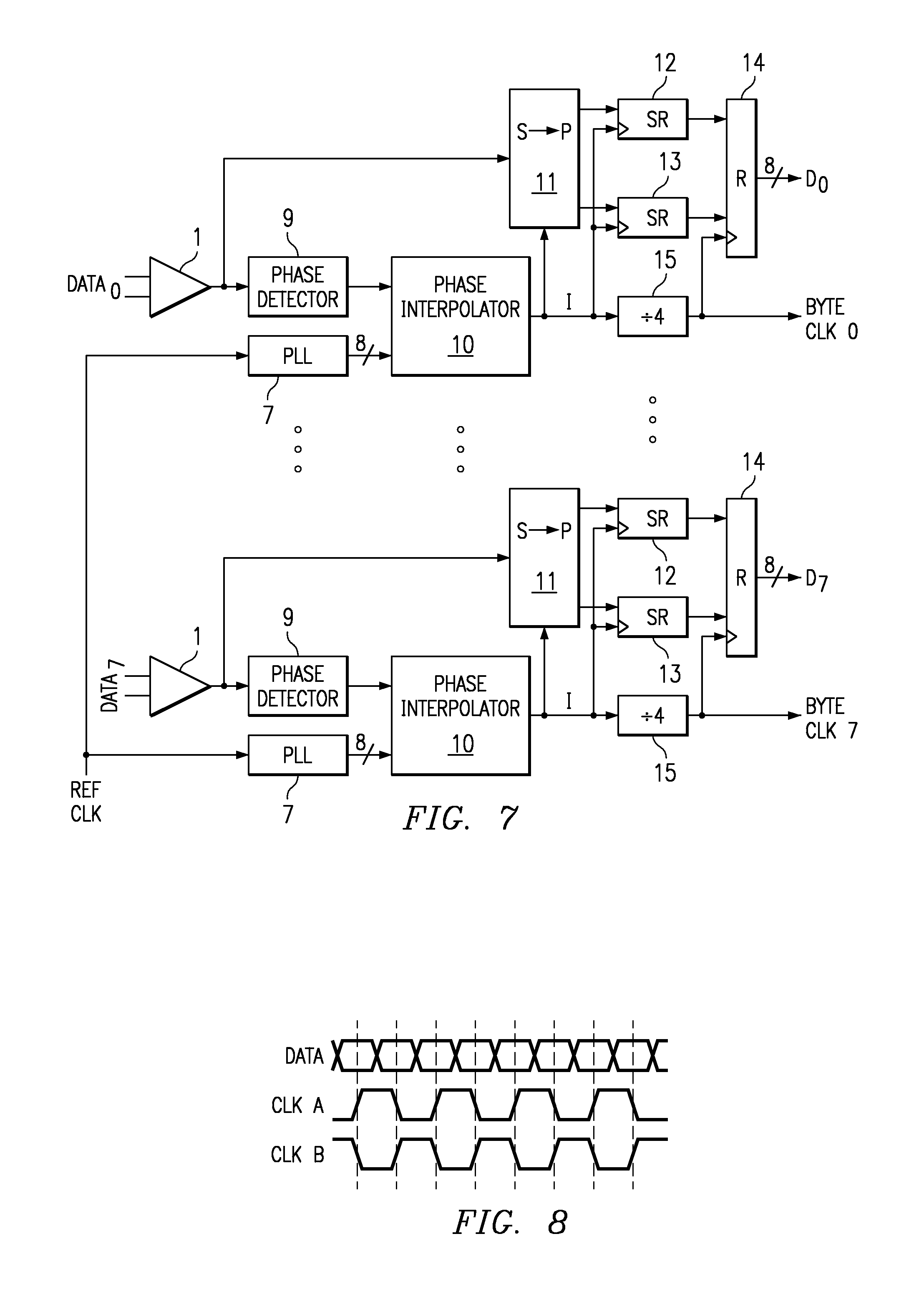
There are difficulties, the inventors have realised, with applying a circuit such as that of FIG. 5 to plural serial data streams in parallel.

Method used


Image

  • Data transmission
  • Data transmission
  • Data transmission

Examples


first embodiment

[0127]The problem of anti-phase clocks is solved in the present invention, by specifying one of the channels as having the master bit clock and aligning each of the generated bit clock signals to that master bit clock.

[0128]Refer to the phase wheel of FIG. 4 and assume that the master channel produces a bit clock with a relative phase of 0° so that the phase of all of the generated bit clocks can be plotted on the phase wheel relative to the phase of the bit clock of the master channel. As discussed above, the phase of any generated bit clock relative to the master bit clock could in general be at any point around the phase wheel. This is because each of the bit clocks is generated independently with reference only to the data stream in that channel.

[0129]In order for the anti-phase bit clock problem of FIG. 8 to be avoided, all of the bit clock signals should, the inventors have realised, be within the same half of the phase wheel of FIG. 4 (taking, for example, 0° to be the phase ...

second embodiment

[0131]The bit clock phase signal produced by each of circuits 17, 18 and 19 is passed to a central controller 16. That controller 16 compares the phase of each bit clock with the phase of the master bit clock. If the phase difference between a bit clock and the master clock is greater than 90° such that the bit clock is in the wrong half of the phase wheel a spin signal for that bit clock is generated. (Since the phase of a clock is represented by digital values (a pair of them as mentioned above), a combinatorial logic circuit is provided that calculates whether the difference is more than 90°, for example a phase comparator as described below in the ) When any one of circuits 17, 18 or 19 receives a spin command, that circuit forces the phase of the bit clock of that channel to be changed by 180°. This is done preferably by switching an inverter in or out of the path of the bit clock signal. A deglitching switch is provided to ensure that the inverter does not introduce extra edge...


PUM


Abstract

A circuit for receiving multiple serial datastreams in parallel is disclosed. A bit clock is recovered from each data stream, there being one data bit for each transition of the clock signal both positive and negative going. The phases of the bit clocks are compared and are adjusted by 180 degrees so that the positive going edges of all occur close to each other. The bits of each stream are assembled into words under the control of a word clock. In one embodiment a common word clock is derived form the set of bit clocks as a whole. In another embodiment each stream is provided with its own word clock which is aligned to positive edges of the respective bit clocks that are close to each other.

Description

FIELD OF THE INVENTION[0001]The present invention relates to the transmission of data and more particularly to the transmission of a number of serial data streams in parallel.BACKGROUND OF THE INVENTION[0002]FIG. 1 shows a differential driver 1 that takes a differential input on conductors 2 and 3 and converts that input into a serial data stream on an output conductor 4.[0003]It is known to use the differential driver 1 of FIG. 1 as an input stage to a digital system, but other circuits for that purpose are known. It is also known to generate a clock signal for the digital system from an input data stream (i.e. on the output 4 of the differential driver 1 in the case of FIG. 1). Such clock recovery is especially effective when the data changes frequently as this makes it easier to determine where the clock pulses should be positioned.[0004]FIG. 2 shows a single data stream and an associated clock signal. The clock signal shown in FIG. 2 samples the data on both the rising and falli...

Claims


Application Information

Patent Timeline
Patent Type & Authority Patents(United States)
IPC IPC(8): H04L25/00H04L7/04H04L7/033H04L25/14
CPCH04L25/14H04L7/0337
Inventor JOY, ANDREWSIMPSON, ROBERTWARD, RICHARD
Owner TEXAS INSTR INC
Learn More