Fixing device, image forming device, and manufacturing method of fixing device

a technology of fixing device and manufacturing method, which is applied in the direction of ohmic-resistance heating, shafts and bearings, instruments, etc., can solve the problems of prolonging warm-up time, requiring a longer warm-up time, and poor warm-up performance, and achieve the effect of short tim

Active Publication Date: 2007-01-30
SHARP KK
View PDF8 Cites 12 Cited by
  • Summary
  • Abstract
  • Description
  • Claims
  • Application Information

AI Technical Summary

Benefits of technology

[0012]An object of the present invention is to provide a fixing apparatus capable of realizing high-speed printing by transmitting heat to the toner and the recording medium in a short time.
[0015]As a result of diligent studies, the inventors of the present invention found out that it is easy to transmit heat to the fix member but it is difficult to transmit, to the press member, the heat thus transmitted to the fix member, thereby efficiently utilizing, for fixing operation, the heat transmitted to the fix member, where in the fixing device the heat transmission coefficient K1 of the press member and the heat transmission coefficient K2 of the fix member satisfy (100·K1)≦(K2)≦(320·K1). With this arrangement, it is possible to transmit the heat from the fixing device to the toner and the recording medium in a short time, thereby realizing the high-speed printing.

Problems solved by technology

The fix member, if thinner than the conventional fix member, may require a longer warm-up time (may have a poor warm-up performance), depending on the balance of the heating and adiabatic performance of the fix and press members between which the recording material is transferred.
The extension of warm-up time will reduce convenience.
Adverse effects are not limited to the warm-up time extension; the warm-up time extension results in higher power consumption level in standby mode, against the popular trend of energy conservation.
However, if the balance of the heating and thermal insulating (adiabatic) performance of the fix and press members is anything less than desirable, the device consumes more power in the heating of the recording material for the fixing, thereby adversely affecting the overall energy saving performance by the image forming device.
The warm-up performance especially affects power consumption in warm-up and standby, as well as convenience in use.
Further, the power available for the image forming device to perform the heating and fixing of the recording material are so limited.
In some cases, the image forming device would be undesirably underpowered depending on various power supply conditions, such as a number of periphery devices added, countries or regions the image forming device is used, etc.
It however faces structural problems of the silicone sponge press member itself and the fix member, when applied to high speed, heavy load conditions.
This however would make the air bubbles in the silicone sponge easy to collapse, thereby leading to permanent deformation of the silicone sponge, depriving the required level of elasticity from the silicone sponge.
The silicone sponge or like elastic body could permanently deformed markedly at near a surface thereof, thereby leading to lower thermal adiabatic performance of the press member.
This would result in the nip with too large width, and thus excessive fixing.
The excessive fixing leads to inconveniences like high temperature offset and twining.
When the permanent deformation of the press member is further progressed, the press member cannot sustains its elasticity by which it can function as it is.
Such loss of elasticity shortens life of the press member and the device to which the press member is provided.
As described above, the use of silicone sponge for the press member is associated with the various problems in order to deal with the high speed and heavy load, thus it is difficult to realize high-speed printing by the use of silicone sponge for the press member.

Method used


Image

  • Fixing device, image forming device, and manufacturing method of fixing device
  • Fixing device, image forming device, and manufacturing method of fixing device
  • Fixing device, image forming device, and manufacturing method of fixing device

Examples


first embodiment

[0056][First Embodiment]

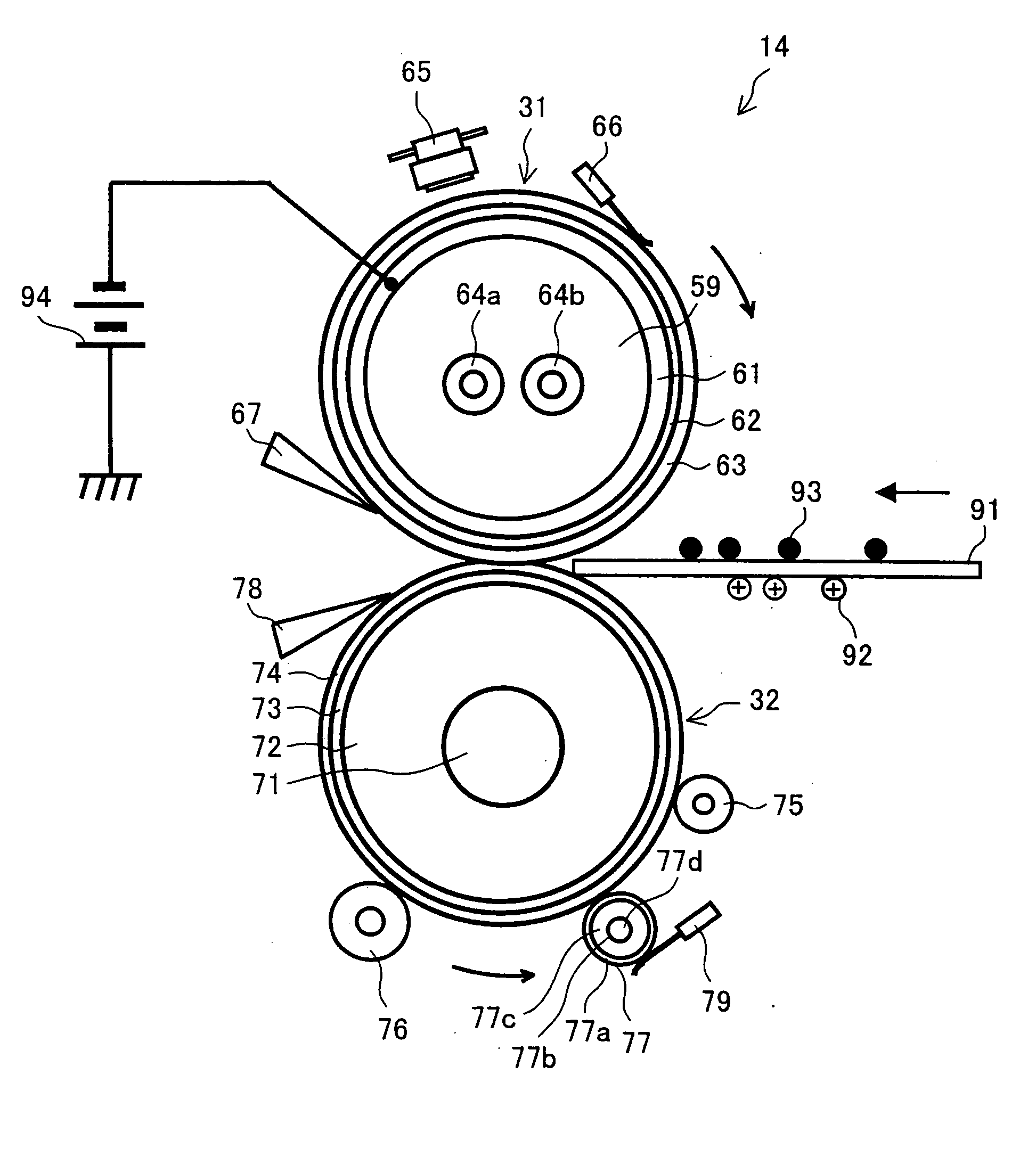
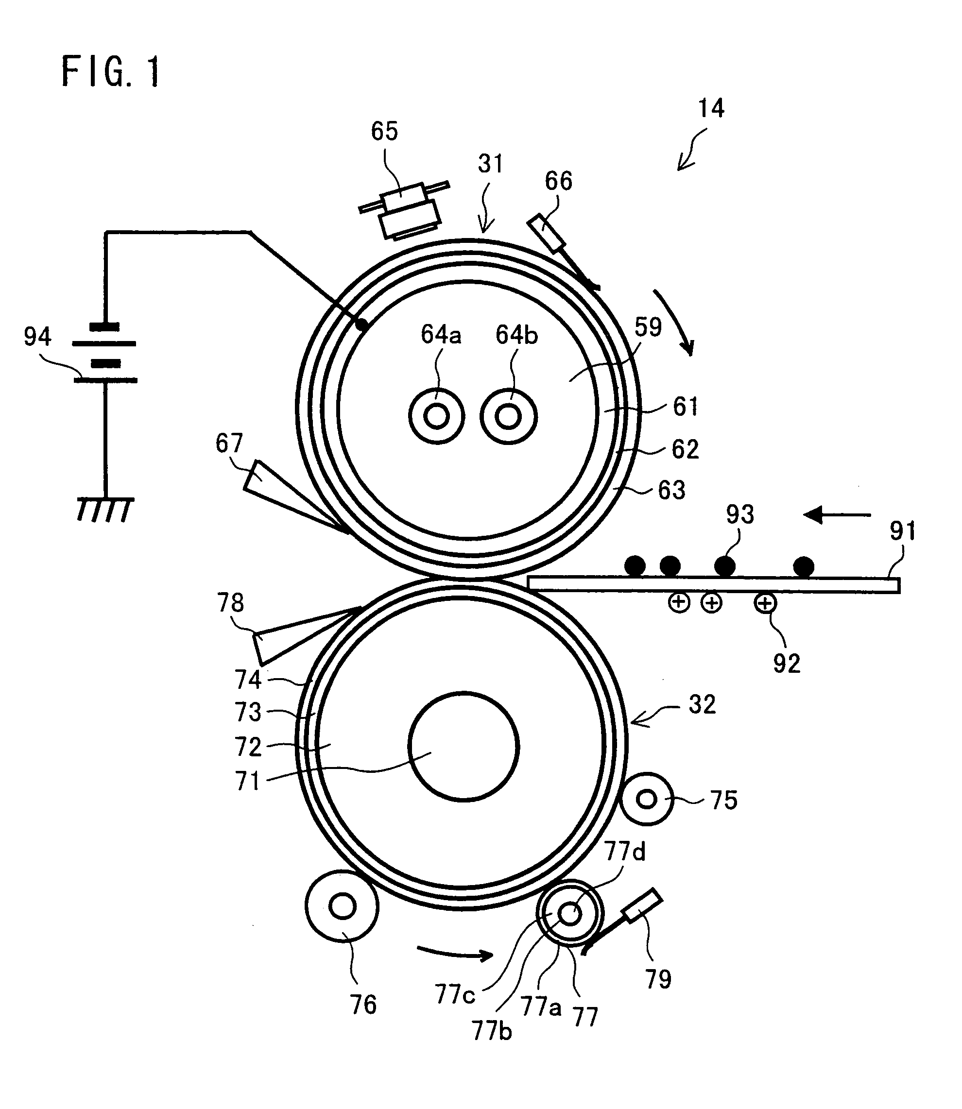
[0057]Referring to FIG. 1, an example of an arrangement of a fixing device of an image forming device according to the first embodiment will be described below.

[0058]FIG. 1 illustrates details of a structure of the fixing device 14. FIG. 1 is a vertical cross sectional view illustrating the fixing device 14. In the fixing device 14, a fix roller 31, which is a fix member in a roller form, is internally provided with a core 61 that is conductive (and may be a metal core), whereas a press roller 32, which is a press member, is internally provided with a core 71 that is conductive (and may be a metal core).

[0059]The fix roller 31 is formed with the core 61 as a base member, and is 40 mm in external diameter and 1.3 mm in thickness (thickness of a layer without the core). The core 61 is formed to have a predetermined external diameter and thickness by subjecting an iron-type cold rolled carbon steel tube to drawing process or the like, and then polishing the thus...

second embodiment

[0169][Second Embodiment]

[0170]Referring to FIGS. 10 and 11, another embodiment of the present invention is described below. Note that a fixing device according to the present embodiment has a basic structure same as that in the firs embodiment. Thus, explanation on the same member and feature is omitted here.

[0171]As in the first embodiment, the fixing device 121 of the present embodiment has a fix member (fix roller 97) and a press member (press roller 97), each of which is in a roller shape and has a conductive core. The fix roller 97 is provided with, for example, a core 98, an intermediate layer 62, and a releasing layer 63. The core 98 is narrowed at respective ends and has an external diameter of 40 mm.

[0172]The intermediate layer 62 and the releasing layer 63 are identical with those corresponding members in the first embodiment. The fix roller 97 of the present embodiment is different from the fix roller 31 of the first embodiment in terms of thickness (wall thickness) of t...

third embodiment

[0209][Third Embodiment]

[0210]Still another embodiment of the present invention is explained below, referring to FIG. 18. Note that the explanation on the members identical to the corresponding member in the first embodiment is omitted here.

[0211]A fixing device 114 of the present embodiment is mainly applicable to a color image forming device. In the fixing device 114, a fix belt 131 is held by a driving roller 134 and a driven roller 135. Further there provided a heating roller 77 for heating the fix belt 131. The heating roller 77 also functions as a tension roller.

[0212]In the present embodiment, the fix belt 131 in the belt-like shape is provided as the fix member. The fix belt 131 is provided with a base belt (core) 132, a releasing layer 133, and a primer (intermediate layer) 136.

[0213]The base belt 132 is 125.7 mm in circumferential length and 0.55 mm in belt thickness (thickness), and is prepared from a Ni layer of 0.5 mm in thickness. (layer thickness). Moreover, on the ba...


PUM


Abstract

A fixing device comprising a fix member for touching an unfixed image on a recording medium, and a press member for being pressed against the fixing member, so as to fix the unfixed image on the recording medium by transporting the recording medium through a nip between the fix member and the press member, wherein (100·K1)≦(K2)≦(320·K1) where K1 is a heat transmission coefficient of the press member and K2 is a heat transmission coefficient of the fix member. With this arrangement, it is possible to transmit heat to toner and the recording medium in a short time. Thus, it is possible to attain high-speed printing.

Description

[0001]This Nonprovisional application claims priority under 35 U.S.C. § 119(a) on Patent Application No. 2003-393917 filed in Japan on Nov. 25, 2003, the entire contents of which are hereby incorporated by reference.FIELD OF THE INVENTION [0002]The present invention relates to fixing devices in, among others: electrophotographic image forming devices in copying machines and printers; drier devices in electrophotographic devices of wet types; drier devices in inkjet printers; and rewriteable medium eraser devices.BACKGROUND OF THE INVENTION[0003]In conventional image forming device and like devices, a fixing process is carried out for fixing toner onto a recording material. In the fixing process, a toner image formed with toner or the like on the recording material in an image forming process in an upstream of the fixing process is heated so that the toner is melted and fixed onto the material, while the recording material is being transported between two cylindrical members, namely ...

Claims


Application Information

Patent Timeline
Patent Type & Authority Patents(United States)
IPC IPC(8): G03G15/20F16C13/00
CPCG03G15/2064
Inventor MITSUOKA, TETSUNORIKIDA, HIROSHIKAGAWA, TOSHIAKIYAMANAKA, TAKASHI
Owner SHARP KK
Why Eureka
Try Eureka