Clamp unit for Do-It-Yourself (DIY) solid wood flooring

a technology of solid wood flooring and clamping unit, which is applied in the direction of walls, flooring, building components, etc., can solve the problems of large labor costs, deformation of panels, and deformation of entire flooring, and achieve the effect of maximizing the flexibility of adjustmen

Inactive Publication Date: 2007-02-06
MEI TZU CHIANG
View PDF1 Cites 23 Cited by
  • Summary
  • Abstract
  • Description
  • Claims
  • Application Information

AI Technical Summary

Benefits of technology

[0012]It is a primary object of the invention to provide a clamp unit for DIY solid wood flooring. Each clamp unit is made up of two individual clamps laid side-by-side with a spring clip between the conjunction points. This allows each clamp to move in accord with the solid wood panel that is laid on top of it. There is no concern of breaking because the gap between the panels can be adjusted, thereby increasing its bondage strength as well as its usage life.
[0013]It is another object of the invention to provide a clamp unit for DIY solid wood flooring that can increase the convenience to the consumer. The two clamps that make up the single clamp unit can be separated and used individually, which allows the clamps to be applied to the front and back ends of the solid wood panels.
[0014]It is a further object of the invention to provide a clamp unit for DIY solid wood flooring which increases the scope of application because it can match the needs of various floor shape configurations.

Problems solved by technology

If the panels are not laid properly, expansion and contraction will cause the panels to deform after a while, and the entire flooring must be changed.
Because of this, labor costs are often much higher than the cost of the wood material, resulting in higher overall construction costs and additional financial burden to the user.
Furthermore, floor panel layers are often hard to hire if the construction project is small or for only partial interior decoration.
Severing is no easy task for the DIY consumer, especially since the clamp 1 is made from hard plastic material and has a slippery surface.
Consumers are often hurt when trying to sever the clamp.
In addition, the other disadvantage of the aforementioned clamp 1 is shown in FIGS. 4A, B, i.e. the reserved gap left between the conjunction points T1 when solid wood panels 2a and 2b are laid together.
The disadvantage to this type of clamping track 3 is that it must be laid out in parallel, i.e. it is only suited for square or rectangular shape floor spaces.
Yet many homes have floor spaces that are irregularly configured circular or slanted, etc., which makes these types of clamps unsuitable.
Due to its configuration limitations, these clamps are not widely used, which is one of its disadvantages.
This allows the last solid wood panel to easily come off, leading to the problem of loose bondage between the solid wood panels.

Method used


Image

  • Clamp unit for Do-It-Yourself (DIY) solid wood flooring
  • Clamp unit for Do-It-Yourself (DIY) solid wood flooring
  • Clamp unit for Do-It-Yourself (DIY) solid wood flooring

Examples


Embodiment Construction

[0031]First of all, referring to FIGS. 7 and 8, the clamp unit 7 in accordance with the invention includes a first clamp 4 and a second clamp 5, as well as two spring clips 6.

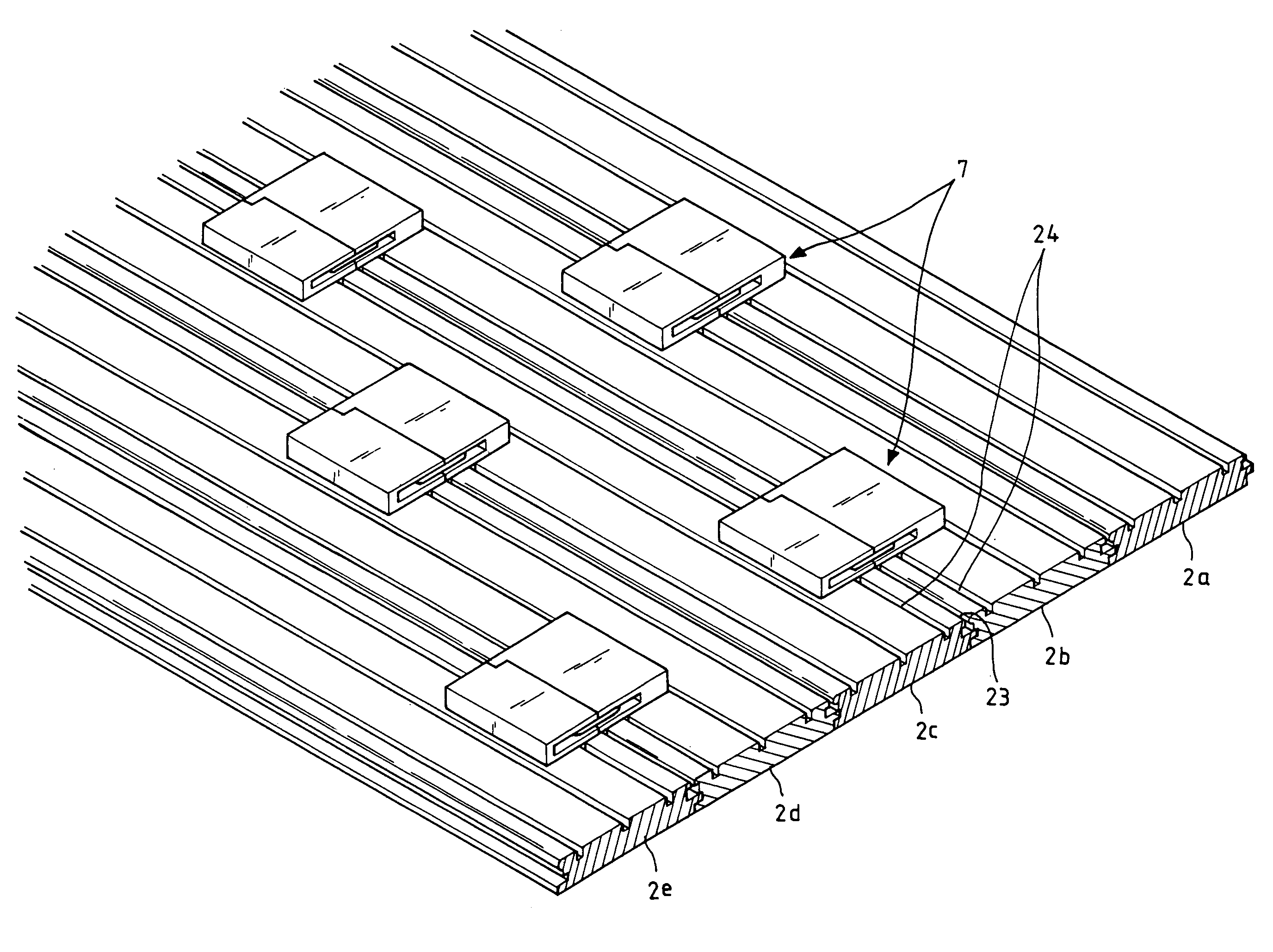
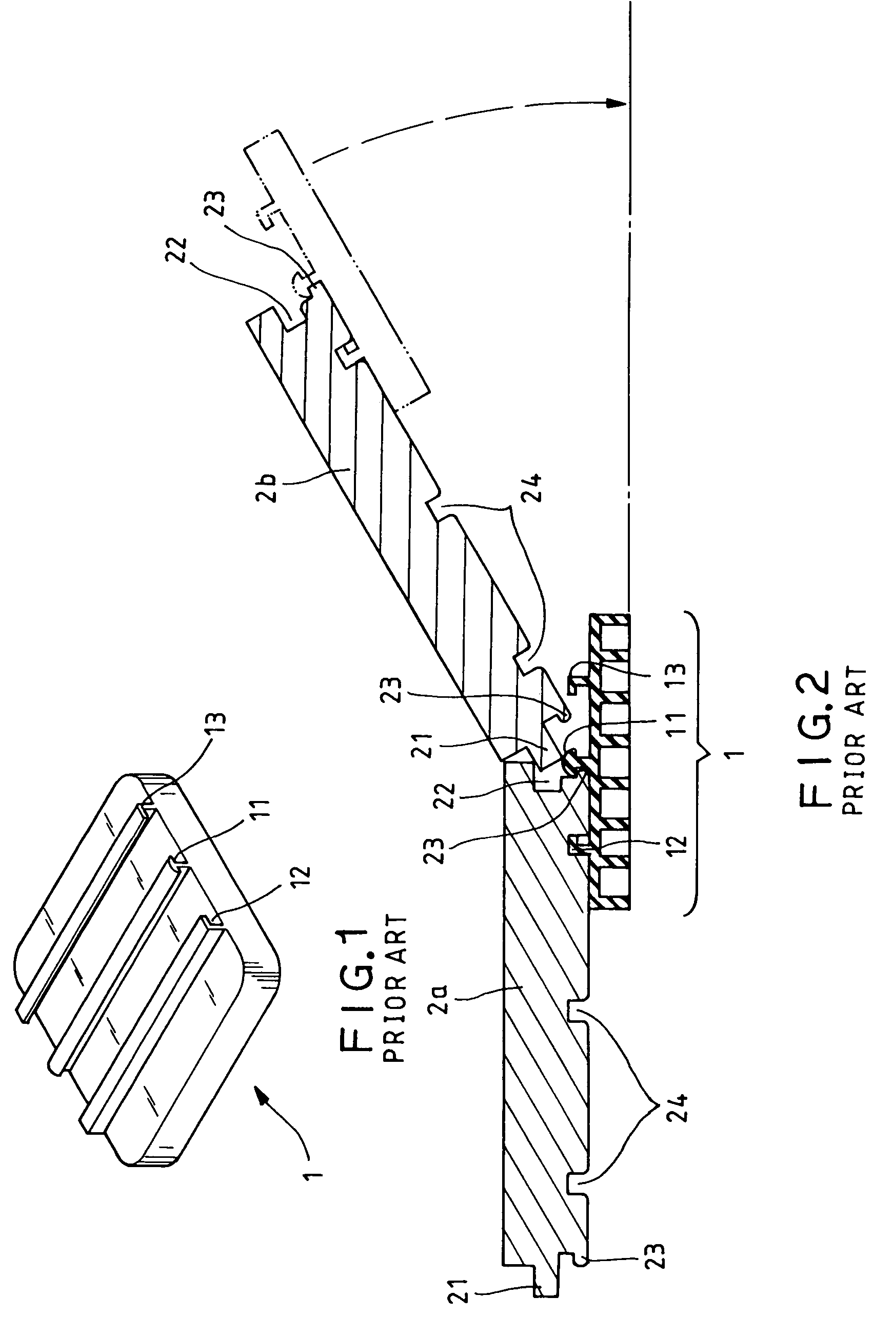
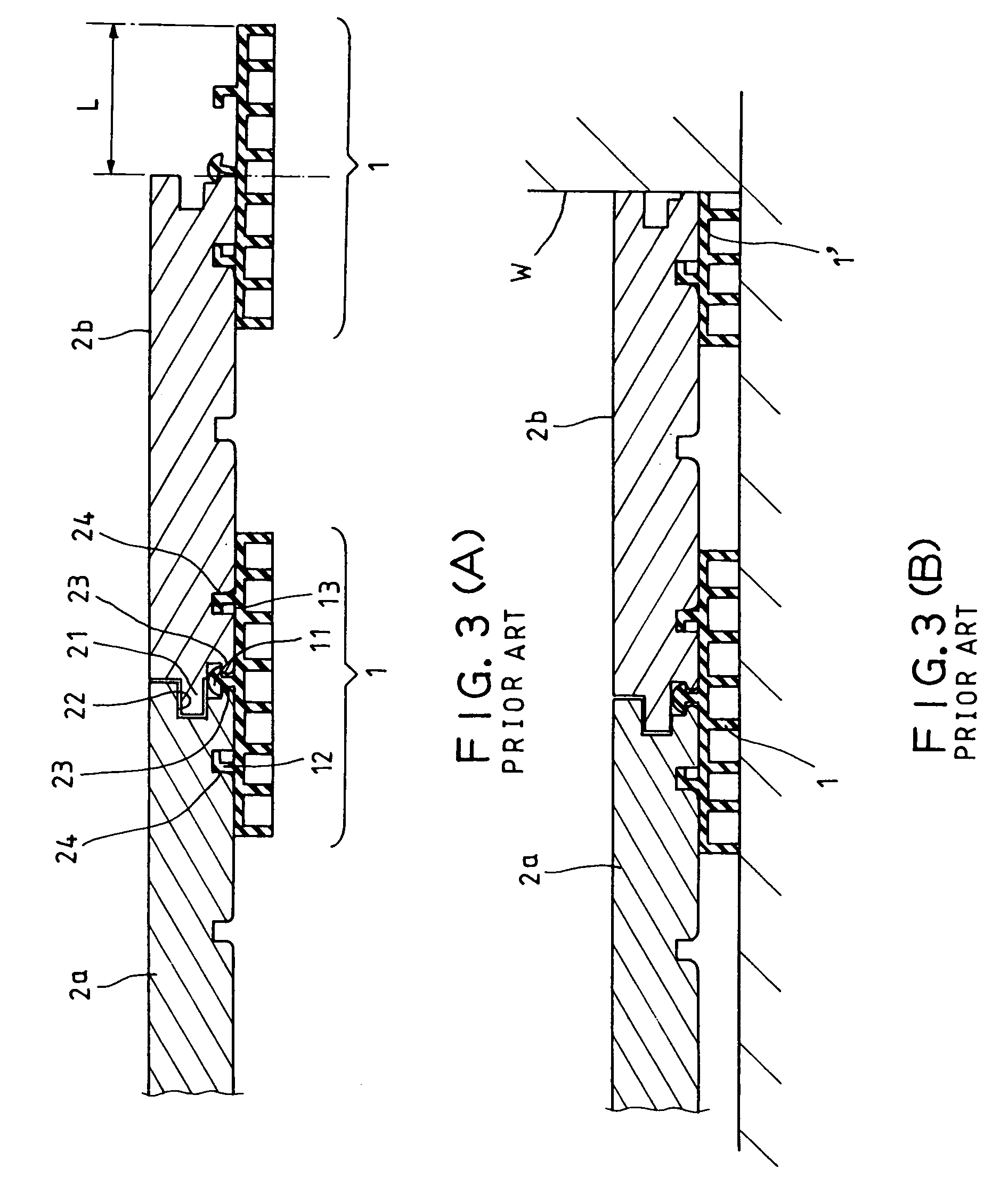
[0032]The upper surface of the first clamp 4 matches the groove side of a solid wood panel and has a first protrusion 41 on it. The mentioned solid wood panel is of regular market specification and installation technique as mentioned in FIG. 2 so that no further descriptions thereto are given hereinafter.

[0033]A T-shape protrusion 42 is disposed at the junction of two adjacent solid wood panels that matches the groove on the bottom side of the solid wood panel. Moreover, a tongue 43 is formed on its inner side of the first clamp 4 and extended along a first clamp groove 44.

[0034]A second protrusion 51 is formed on the upper surface of the second clamp 5 that matches the groove on the bottom side of the solid wood panel as shown in FIGS. 11, 12. A groove 52 is formed at the inner side of the second clamp 5 and m...


PUM

PropertyMeasurementUnit
depthaaaaaaaaaa
depthaaaaaaaaaa
durableaaaaaaaaaa

Abstract

The invention relates to a clamp unit for Do-It-Yourself (DIY) solid wood flooring having a first clamp, a second clamp and two spring clips. The first clamp includes a first protrusion, a T-shape protrusion disposed at the junction of two adjacent solid wood panels, and a tongue formed on the inner side of the first clamp and extended along a first clamp groove. The second clamp includes a second protrusion, a groove formed at the inner side of the second clamp and matching the tongue of the first clamp for engaging into each other, and a second clamp groove formed inside of the second clamp. The spring clips each include an opening mouth that fits tightly into the first and second grooves so that the first and second clamp are merged into one clamp unit. This allows the gap between the solid wood panels to automatically adjust and is suitable for irregular floor configurations.

Description

BACKGROUND OF THE INVENTION[0001]1. Field of the Invention[0002]The invention relates to a clamp unit for Do-It-Yourself (DIY) solid wood flooring, and more particularly, to a clamp which can automatically adjust its clamping structure in accordance with the expansion and contraction of the solid wood panels and is especially suited for wood flooring used to cover irregular shape floors.[0003]2. Description of the Related Art[0004]Solid wood flooring provides a durable surface that is widely received by house owners for its natural warmth and beauty. However, solid wood flooring is made up of separate wood panels laid side-by-side. Therefore, the gap left between each wood panel is of utmost importance and must rely on the craft and skill of the floor panel layer. If the panels are not laid properly, expansion and contraction will cause the panels to deform after a while, and the entire flooring must be changed. Because of this, labor costs are often much higher than the cost of the...

Claims


Application Information

Patent Timeline
Patent Type & Authority Patents(United States)
IPC IPC(8): E04B2/00E04B1/00E04F15/04
CPCE04F15/04E04F2201/0517E04F2201/0153
Inventor MEI, TZU-CHIANG
Owner MEI TZU CHIANG
Why Eureka
Try Eureka