Method of manufacturing friction plate

a technology of friction plate and core plate, which is applied in the direction of friction lining, synthetic resin layered products, mechanical instruments, etc., can solve the problems of easy deformation of core plate, and inability to maintain accurate clearance of core plate with respect to opponent members, etc., to achieve short period of time and enhance production efficiency

Active Publication Date: 2007-02-06
NSK WARNER
View PDF3 Cites 0 Cited by
  • Summary
  • Abstract
  • Description
  • Claims
  • Application Information

AI Technical Summary

Benefits of technology

[0014]It is an object of the present invention to enhance the production efficiency of manufacturing a friction plate when the adhesive is dried and cured by a small-scale apparatus and further the drying and curing time is shortened.
[0016]According to the present invention, the adhesive is dried and cured by means of high-frequency heating for heating the core plate. Therefore, the adhesive can be dried and cured by a small-scale apparatus in a short period of time. Accordingly, the production efficiency can be enhanced.

Problems solved by technology

However, when blasting is conducted on the core plate, the core plate tends to be deformed easily.
Further, the peripheral devices tend to be abraded by powder used in the process of blasting.
Further, concerning the method of coating the adhesive, such a problem is solved in the conventional example that the adhesive attaches to an inner circumference of the core plate and clearance of the core plate with respect to the opponent member can not be maintained accurate.
However, in the conventional method of coating the adhesive, the following problems may be encountered.

Method used


Image

  • Method of manufacturing friction plate
  • Method of manufacturing friction plate
  • Method of manufacturing friction plate

Examples


embodiments

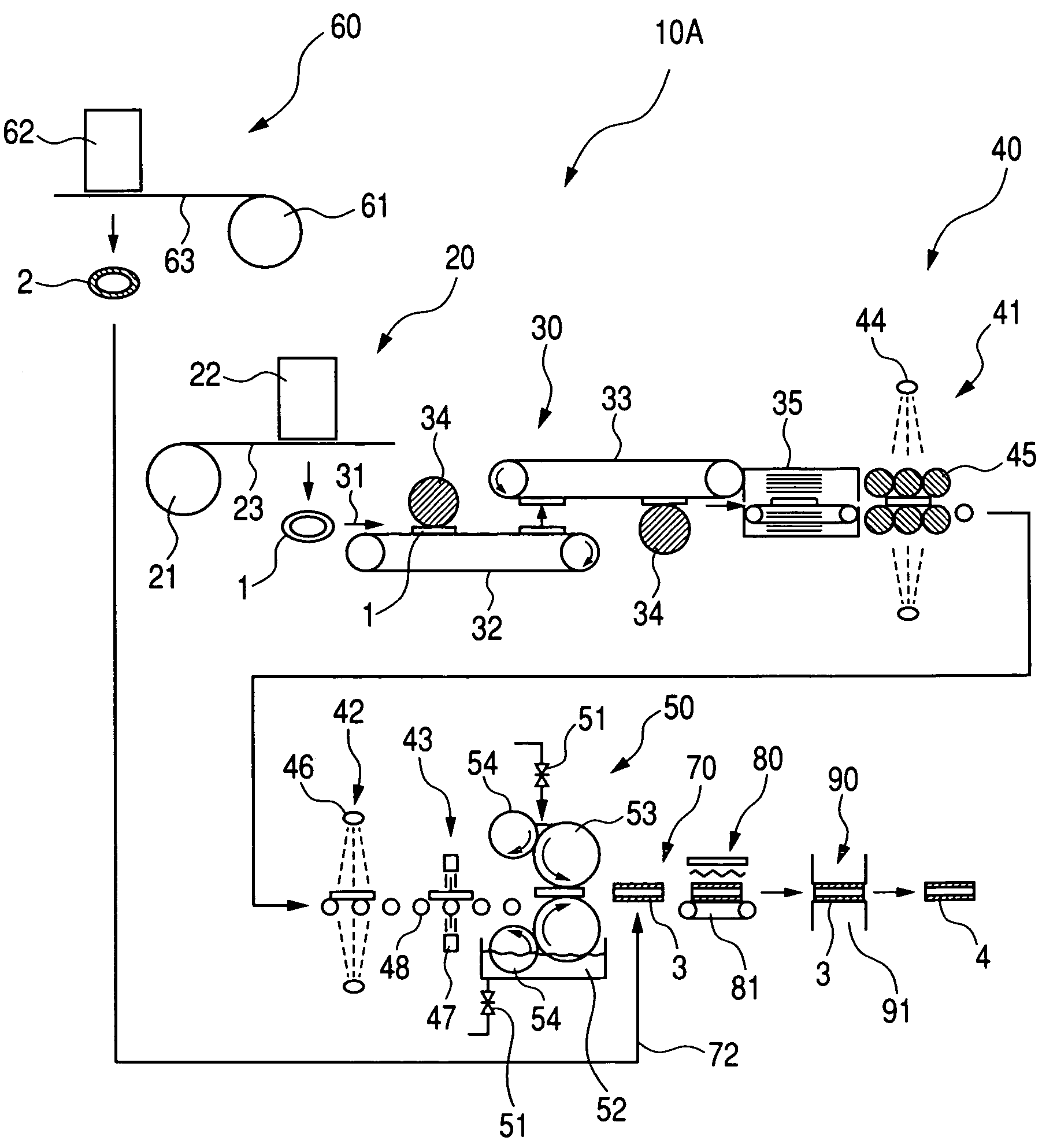
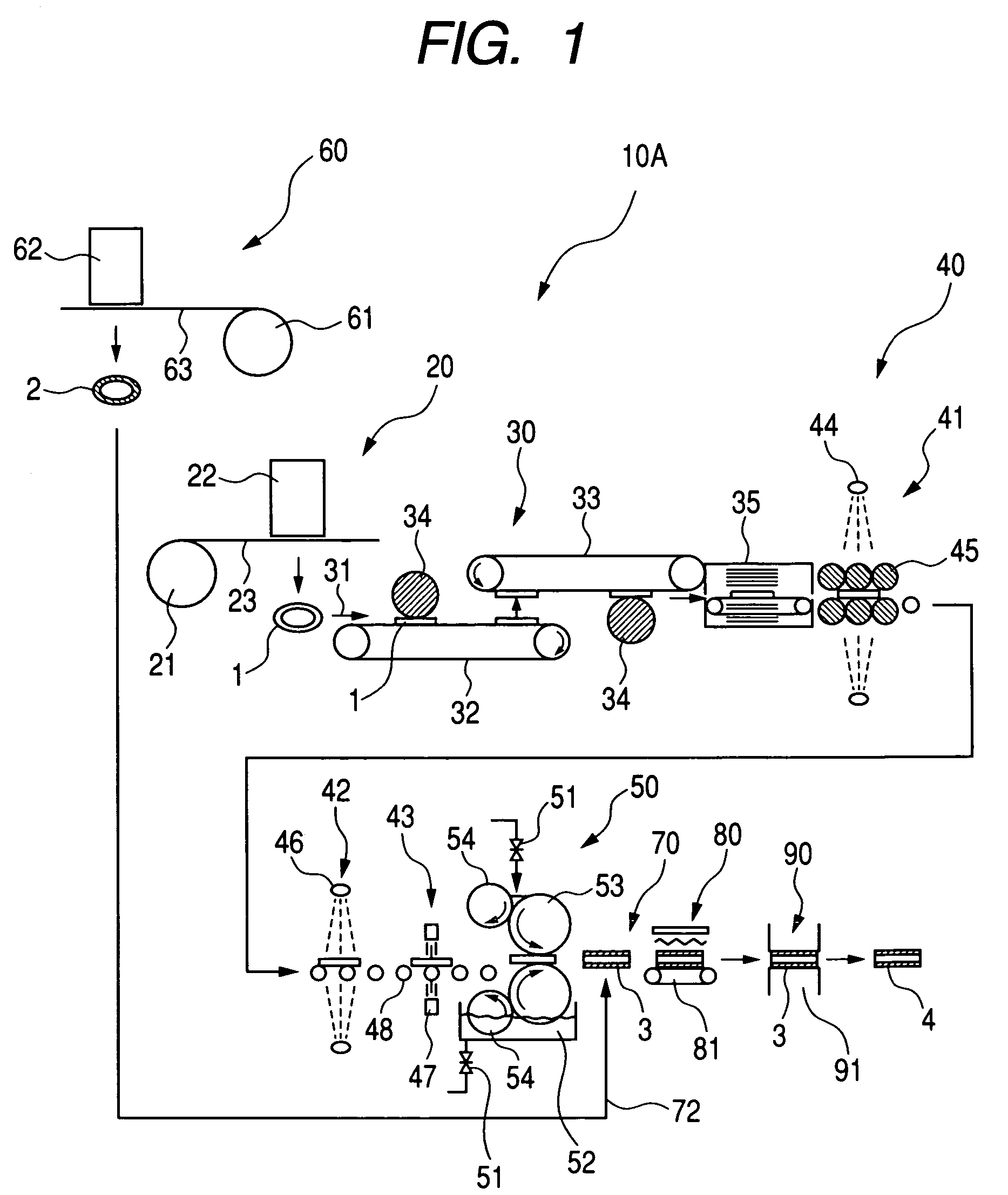
[0026]FIG. 1 is a view showing a flow 10A of the process of the first embodiment of the present invention. Reference numeral 20 defines a punching step of the core plate, reference numeral 21 defines a metallic strip roll, reference numeral 22 defines a punching machine, reference numeral 23 defines a metallic strip which has been drawn out from the metallic strip roll 21, and reference numeral 1 defines a core plate which has been punched into a predetermined shape.

[0027]Reference numeral 30 defines a core plate surface roughing step. As shown by arrow 31, the core plate 1 punched into the predetermined shape is supplied onto the conveyer 32 and the surface of the core plate 1 is roughed by the buffing roller 34. Next, the core plate 1 is attracted by the next magnetized conveyer 33, and the opposite surface of the core plate 1 is roughed by the buffing roller 34. After that, the core plate 1 is demagnetized by the demagnetizer 35 and then conveyed to the next cleaning step 40.

[002...


PUM

PropertyMeasurementUnit
widthaaaaaaaaaa
widthaaaaaaaaaa
widthaaaaaaaaaa

Abstract

A core plate 1, which has been punched in a core plate punching step 20, is conducted a surface roughing step 30 and a cleaning step 40. After coating both surfaces of the core plate 1 with adhesive in an adhesive coating step 50, the core plate 1 is put on a friction member 2, which has been punched in a friction member punching step 60, in a piling step 70, and a piled body 3 is conveyed to a drying and curing step 80. The core plate 1 is heated by high-frequency heating to dry and cure the adhesive. The core plate 1 and the friction member 2 are heated and pressured by the hot press 91, and the friction plate 4 is completed. Since high-frequency heating is adopted, an apparatus can be downsized, working time can be reduced and production efficiency can be enhanced.

Description

BACKGROUND OF THE INVENTION[0001]1. Field of the Invention[0002]The present invention relates to a method of manufacturing a friction plate used for an automatic transmission. More particularly, the present invention relates to a method of drying and curing adhesive.[0003]2. Description of the Related Art[0004]When manufacturing a friction plate by making a friction member adhere onto a core plate, in conventional, an adhesion face is made to be rough for increasing an adhesive strength of the friction member, and further, as a pretreatment process to be conducted before degreasing and cleaning, sand blasting, degreasing by alkaline detergent, pickling by sulfuric acid and neutralization by a neutralizer is conducted.[0005]However, when blasting is conducted on the core plate, the core plate tends to be deformed easily. Further, the peripheral devices tend to be abraded by powder used in the process of blasting. Further, importance has been recently attached to the environmental pro...

Claims


Application Information

Patent Timeline
Patent Type & Authority Patents(United States)
IPC IPC(8): B32B37/00
CPCB32B37/12B32B37/16B32B38/0012F16D2069/0491B32B38/162B32B2310/0806F16D2069/0475B32B38/04
Inventor TAKAHASHI, RIKIYATAMURA, TOMOYOSHI
Owner NSK WARNER
Why Eureka
Try Eureka