Torch cable disposition structure for arc-welding robot

a technology for arc welding and cable disposition, which is applied in the direction of soldering apparatus, manufacturing tools,auxillary welding devices, etc., can solve the problems of increasing the area of interference with the surrounding, and affecting the stability of the device. , to achieve the effect of stabilizing the position of the torch cable, preventing the generation of large interference areas, and simplifying the device on the forearm

Inactive Publication Date: 2007-02-06
FANUC LTD
View PDF14 Cites 12 Cited by
  • Summary
  • Abstract
  • Description
  • Claims
  • Application Information

AI Technical Summary

Benefits of technology

[0022]According to the present invention, the wire feeder is mounted on a position separate from the forearm. Therefore, a device on the forearm can be simplified and this prevents generation of a large interference area at the back of and above the robot. When the wrist axis of the robot moves, the intermediate fitting section or the intermediate guiding section can limit the movement of the torch cable, thereby stabilizing the posture of the torch cable.
[0023]As a result, an excessive tension and an excessive loosening of the torch cable can be avoided. Even when the wrist moves, a change in the curvature of the torch cable can be minimized, thereby stabilizing the posture of the torch cable. Consequently, it is possible to avoid unstable feeding of the welding wire using the torch cable. Accordingly, the welding quality can be improved.

Problems solved by technology

In these cases, interference can easily occur on the basis of the moving of the arc-welding robot.
Particularly, the torch cable that is connected to the welding torch has a risk of interference with the surrounding work pieces, tools, and peripheral equipment, as compared with the arm and the welding torch, at the front end of the robot, that move in a relatively narrow area.
One of reasons for this is that the torch cable is loosely laid around a robot main body to secure stability of feeding a welding wire, and this increases the area of the interference with the surrounding.
Therefore, when sufficient space is not present around the forearm, the wire feeder has a risk of interference with external devices and wall surfaces.

Method used


Image

  • Torch cable disposition structure for arc-welding robot
  • Torch cable disposition structure for arc-welding robot
  • Torch cable disposition structure for arc-welding robot

Examples


first embodiment

[0050][First Embodiment]

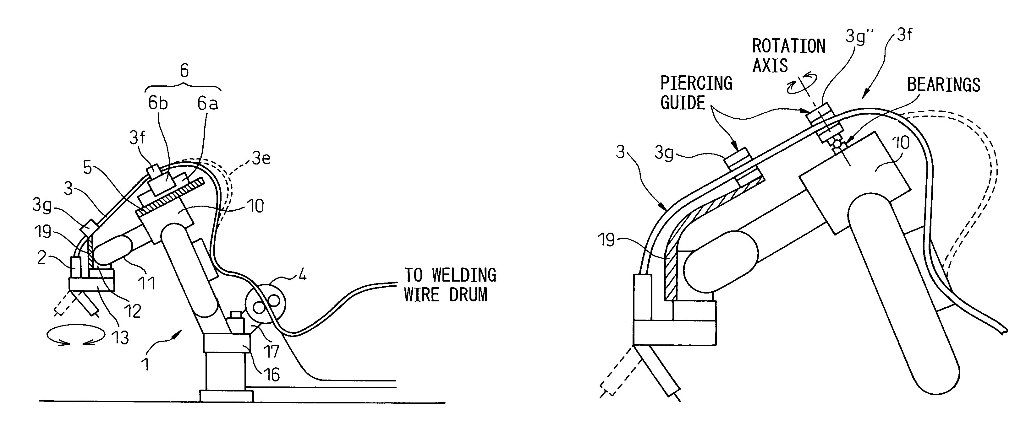
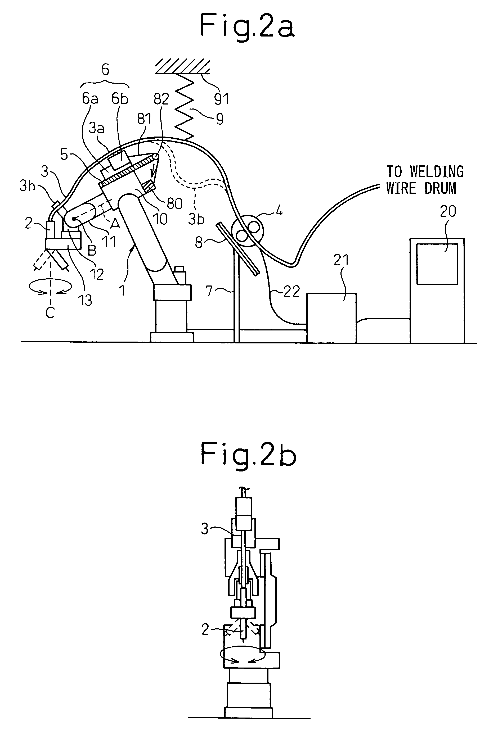
[0051]FIG. 2a and FIG. 2b are a front view and a right side view respectively of a schematic configuration of an arc-welding robot system having a torch cable disposition structure according to the first embodiment of the present invention. The arc-welding robot 1 has six axes. The first wrist element 11 is rotatably provided around the first axis line A, on the front end of the forearm base 10. The second wrist element 12 is rotatably provided around the second axis line B, on the first wrist element 11. The welding torch 2 is rotably supported around the third axis line C via the transmission mechanism 13. The third axis line C is disposed approximately perpendicularly to the second axis line B and is away from the first axis line A with a predetermined distance. In other words, the welding torch 2 is rotatably supported around the axis C parallel with a final rotation axis of the robot offset by a certain amount.

[0052]An example of a supporting and rotatin...

second embodiment

[0070][Second Embodiment]

[0071]FIG. 3a and FIG. 3b are a front view and a right side view respectively of a schematic configuration of an arc-welding robot system having a torch cable disposition structure according to the second embodiment of the present invention. The arc-welding robot according to the second embodiment is different from the arc-welding robot according to the first embodiment in that the installation position of the wire feeder 4 is changed. According to the second embodiment, a wire feeder supporting member 15 is fitted to a suitable position on an upper arm 14 of the robot 1 with a known unit (i.e., a setscrew or the like), and the wire feeder 4 is installed via the wire feeder supporting member 15.

[0072]The torch cable 3 is fixed to the slider 6 at the intermediate fitting section 3a, and is movably held along the longitudinal direction of the forearm (i.e., the forearm base 10 and the second wrist element 12). The torch cable 3 positioned at the back of the sl...

third embodiment

[0074][Third Embodiment]

[0075]FIG. 4a and FIG. 4b are a front view and a right side view respectively of a schematic configuration of an arc-welding robot system having a torch cable disposition structure according to the third embodiment of the present invention. According to the third embodiment, a wire feeder supporting member 17 is fitted to a suitable position on a rotating arm 16 of the robot 1 with a known unit (i.e., a setscrew or the like), and the wire feeder 4 is installed via the wire feeder supporting member 17.

[0076]The torch cable 3 is fixed to the slider 6 at the intermediate fitting section 3a, and is movably held along the longitudinal direction of the forearm (i.e., the forearm base 10 and the second wrist element 12). The torch cable 3 positioned at the back of the slider 6b absorbs the moving amount of the slider 6b between the slider 6b and the wire feeder 4. A reference numeral 3d denotes a looseness that is generated when the moving amount is absorbed.

[0077]A...


PUM

PropertyMeasurementUnit
distanceaaaaaaaaaa
flexibleaaaaaaaaaa
forceaaaaaaaaaa

Abstract

A first wrist element is rotatably provided on the front end of a forearm base of a robot. A second wrist element is rotatably provided on the first wrist element. A welding torch is rotatably supported via a transmission mechanism. A wire feeder is disposed at a position other than a forearm. A torch cable is fitted to a slider with an intermediate fitting section. A slider can be pulled backward by returning a wire connected to a tension generator using a pulley. In place of the fitting section, an intermediate guiding section can be provided.

Description

BACKGROUND OF THE INVENTION[0001]1. Field of the Invention[0002]The present invention relates to a torch cable disposition structure for an industrial robot including an arc-welding torch.[0003]2. Description of the Related Art[0004]As one representative application of a robot, there is an arc-welding robot. The arc-welding robot is an industrial robot that executes arc-welding on a work using an arc-welding torch (hereinafter simply referred to as a “welding torch”) mounted on a part of the robot near the front end of an arm. In a shop floor where the arc-welding robot is used, welding work must be carried out, in many cases, by putting an arm of the arc-welding robot into a narrow space between the work pieces, tools, and peripheral equipment. In these cases, interference can easily occur on the basis of the moving of the arc-welding robot.[0005]Particularly, the torch cable that is connected to the welding torch has a risk of interference with the surrounding work pieces, tools, ...

Claims


Application Information

Patent Timeline
Patent Type & Authority Patents(United States)
IPC IPC(8): B23K9/12B23K9/133B23K37/02B25J17/02B25J19/00
CPCB23K9/1336B25J19/0025B25J17/0283B23K37/02
Inventor INOUE, TOSHIHIKONAKAYAMA, KAZUTAKAIWAYAMA, TAKATOSHI
Owner FANUC LTD
Why Eureka
Try Eureka