Push-pull driver with null-short feature

a technology of push-pull and driver, applied in the direction of electric variable regulation, process and machine control, instruments, etc., can solve the problems of less power efficiency, complicated driving circuitry, and voltage spikes, and achieve the effect of less power consumption, less power consumption, and less power consumption

Inactive Publication Date: 2007-02-06
MICROSEMI CORP
View PDF28 Cites 1 Cited by
  • Summary
  • Abstract
  • Description
  • Claims
  • Application Information

AI Technical Summary

Benefits of technology

[0009]In one embodiment, the present invention proposes a push-pull driver with null-short feature that has advantages of both a conventional full-bridge topology and a conventional push-pull topology. For example, the push-pull driver with null-short feature restores control of circuit behavior when a drive voltage is inactive (or power is not being delivered to a load) without complicating driving control signals or introducing additional losses in a power delivery path. The push-pull driver with null-short feature advantageously allows the use of a push-pull controller to maintain benefits of the conventional push-pull topology while realizing the benefits of the conventional full-bridge topology. In other words, the push-pull controller appears to a transformer and its secondary winding in the push-pull driver with null-short feature as though it is a full-bridge controller.
[0012]The third semiconductor switch and the fourth semiconductor switch are respectively coupled between opposite terminals of the third primary winding and a common voltage (or regulated voltage). The third and the fourth semiconductor switches are active (or on) when the first and the second semiconductor switches are both inactive (or off). Thus, the third primary winding is configured to be short-circuited when power is not delivered to the load. Shorting the third primary winding advantageously freezes (or substantially maintains) the flux state of the transformer core and minimizes losses (or improves power efficiency).

Problems solved by technology

The conventional push-pull topology allows stored energy in the transformer and any tank circuits to leak back into primary winding circuits, often creating voltage spikes across switching transistors coupled to the primary windings.
The conventional full-bridge topology, on the other hand, generally has more complicated driving circuitry and is less power efficient.
In addition, the on-resistance of the upper switches appears as an I2R power loss in the power-delivering path.

Method used


Image

  • Push-pull driver with null-short feature
  • Push-pull driver with null-short feature

Examples


Embodiment Construction

[0019]Although particular embodiments are described herein, other embodiments, including embodiments that do not provide all of the benefits and features set forth herein, will be apparent to those of ordinary skill in the art.

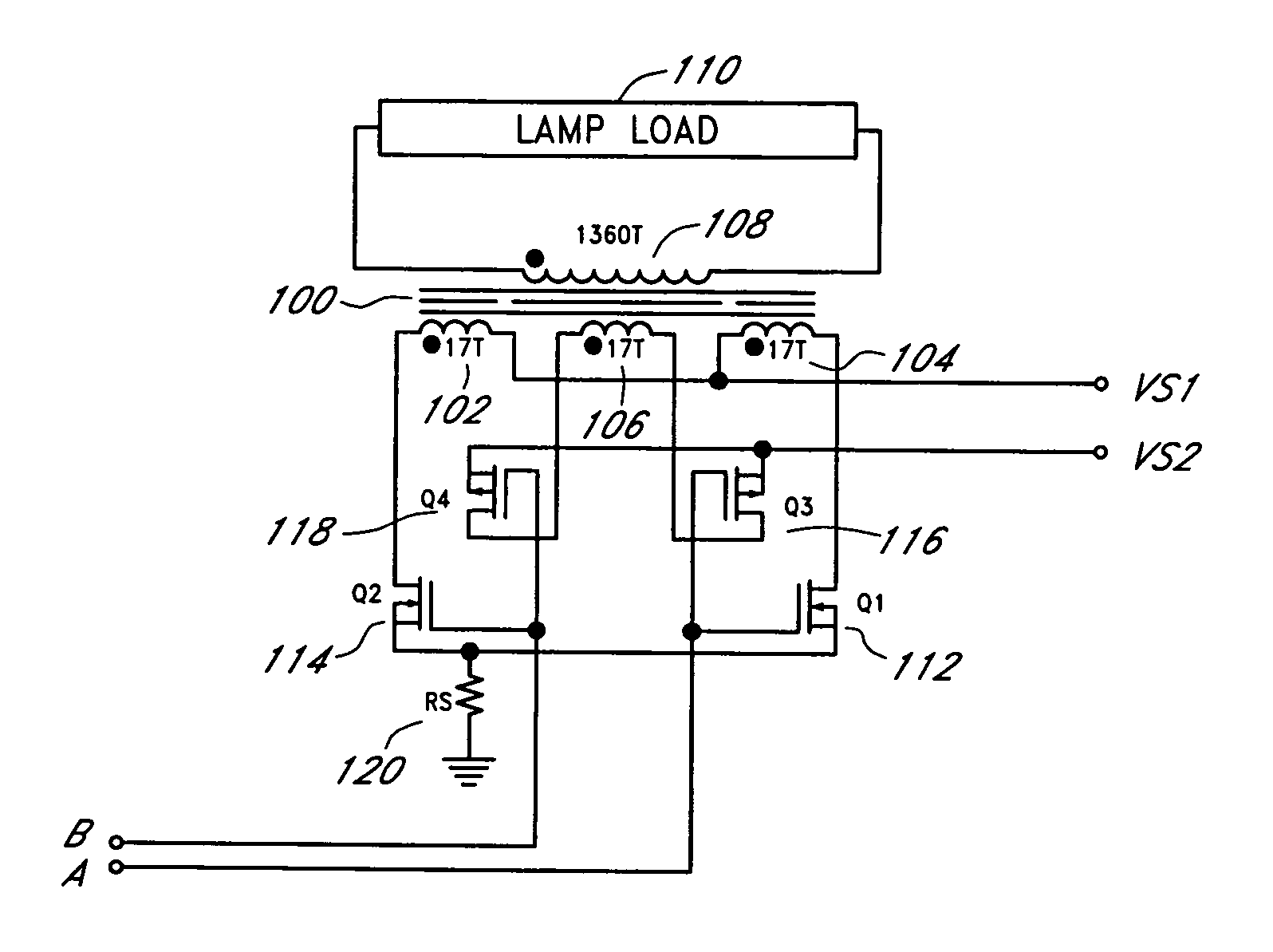
[0020]FIG. 1 illustrates one embodiment of a push-pull driver with null-short feature. The push-pull driver (or inverter) includes a transformer 100 with a first primary winding 104, a second primary winding 102 and a third primary winding 106. A first terminal of the second primary winding 102 and a second terminal of the first primary winding 104 are commonly connected to a power supply (VS1). A lamp load 110 is coupled across a secondary winding 108 of the transformer 100. The lamp load 110 can include one or more CCFLs in a backlight system for LCD applications.

[0021]The push-pull driver also includes four semiconductor switches (or switching transistors) 112, 114, 116, 118 coupled to the transformer 100. The four semiconductor switches 112, 114, 116, 118 ...


PUM


Abstract

A push-pull driver for powering fluorescent lamps in a backlight system includes a transformer with three primary windings to realize the advantages of both a push-pull switching topology and a full-bridge switching topology. The first and the second primary windings alternately conduct currents in opposite polarities to generate an alternating current signal to power one or more lamps coupled to a secondary winding of the transformer. The third primary winding is short-circuited to preserve energy stored in the transformer in a null state when both the first and the second primary windings are not conducting.

Description

CLAIM FOR PRIORITY[0001]This application claims the benefit of priority under 35 U.S.C. § 119(e) of U.S. Provisional Application No. 60 / 591,264, filed on Jul. 26, 2004, and entitled “System and Method for Driving CCFL Backlights Using a Push-Pull Inverter and a Transformer with Three Primary Windings,” the entirety of which is incorporated herein by reference.BACKGROUND[0002]1. Field of the Invention[0003]The invention generally relates to a driver circuit in a backlight system for powering fluorescent lamps, and more particularly, relates to a driver circuit that combines the advantages of a push-pull switching topology and a full-bridge switching topology.[0004]2. Description of the Related Art[0005]In liquid crystal display (LCD) applications, backlight is needed to illuminate a screen to make a visible display. A number of conventional inverter topologies (e.g., active clamping forward, phase-shifted full-bridge, resonant full-bridge, asymmetric half-bridge, push-pull, etc.) fac...

Claims


Application Information

Patent Timeline
Patent Type & Authority Patents(United States)
IPC IPC(8): H05B37/02H02M7/538
CPCH05B41/282H05B41/2824H05B41/2821Y02B20/183
Inventor BALL, NEWTON E.
Owner MICROSEMI CORP
Why Eureka
Try Eureka