
Reconfigurable processor element utilizing both coarse and fine grained reconfigurable elements

a processor element and reconfigurable technology, applied in the field of reconfigurable processor elements, can solve the problems of limited applicability, lack of versatility, and limitation described abov

Inactive Publication Date: 2008-07-29
SRC COMP
View PDF28 Cites 18 Cited by
  • Summary
  • Abstract
  • Description
  • Claims
  • Application Information

AI Technical Summary

Benefits of technology

[0010]However, for this combination to be effective, the two parts must be interconnected with thousands of very high performance interconnects. U.S. patent application Ser. No. 10 / 142,045 discloses, inter alia, two identical parts that are placed on opposite sides of a printed circuit board (PCB). This allows vias through the board to be used to accomplish the thousands of interconnects needed between the two chips. The reconfigurable nature of the FPGAs pins then allows pin assignments to be altered (or programmed) as needed to effectively create two mirror image pin assignments on otherwise identical parts which allows for them to be mounted back to back with like pins being interconnected. While this technique has many advantages, a differing solution is required if two non-identical parts are to be interconnected.
[0024]In addition to the course grained compute functionality described earlier, such course grained chips (some of which may be what is denominated a structured ASIC), may also be used to perform specific interface functions which again use too much fine grained logic, such as Ethernet protocol processing or disk drive protocol processing. In these cases the tight mechanical and electrical coupling between the course and fine grained components, in conjunction with SRC Computer's Intellectual Property dealing with data streaming and flow control in reconfigurable processors, results in greatly improved performance over more electrically distributed solutions while maintaining the benefits of reconfigurable processing.

Problems solved by technology

The limitation described above is due, in part, to the fact that FPGAs are built from fine grain logic elements.
However, building a reconfigurable processor from these devices alone would still lack the versatility that one derives from using fine grained devices which would result in limited applicability.

Method used


Image

  • Reconfigurable processor element utilizing both coarse and fine grained reconfigurable elements
  • Reconfigurable processor element utilizing both coarse and fine grained reconfigurable elements
  • Reconfigurable processor element utilizing both coarse and fine grained reconfigurable elements

Examples


Embodiment Construction

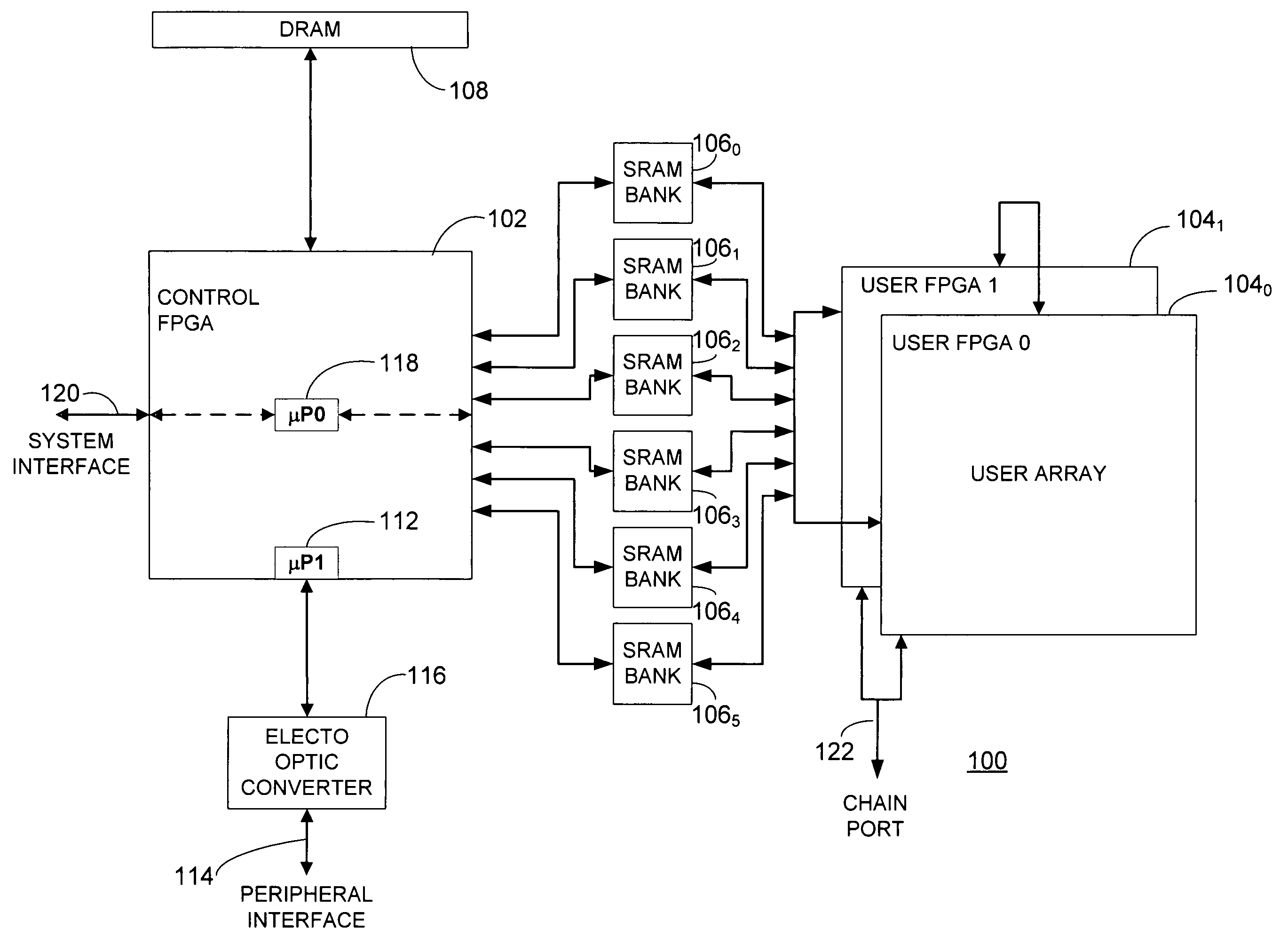
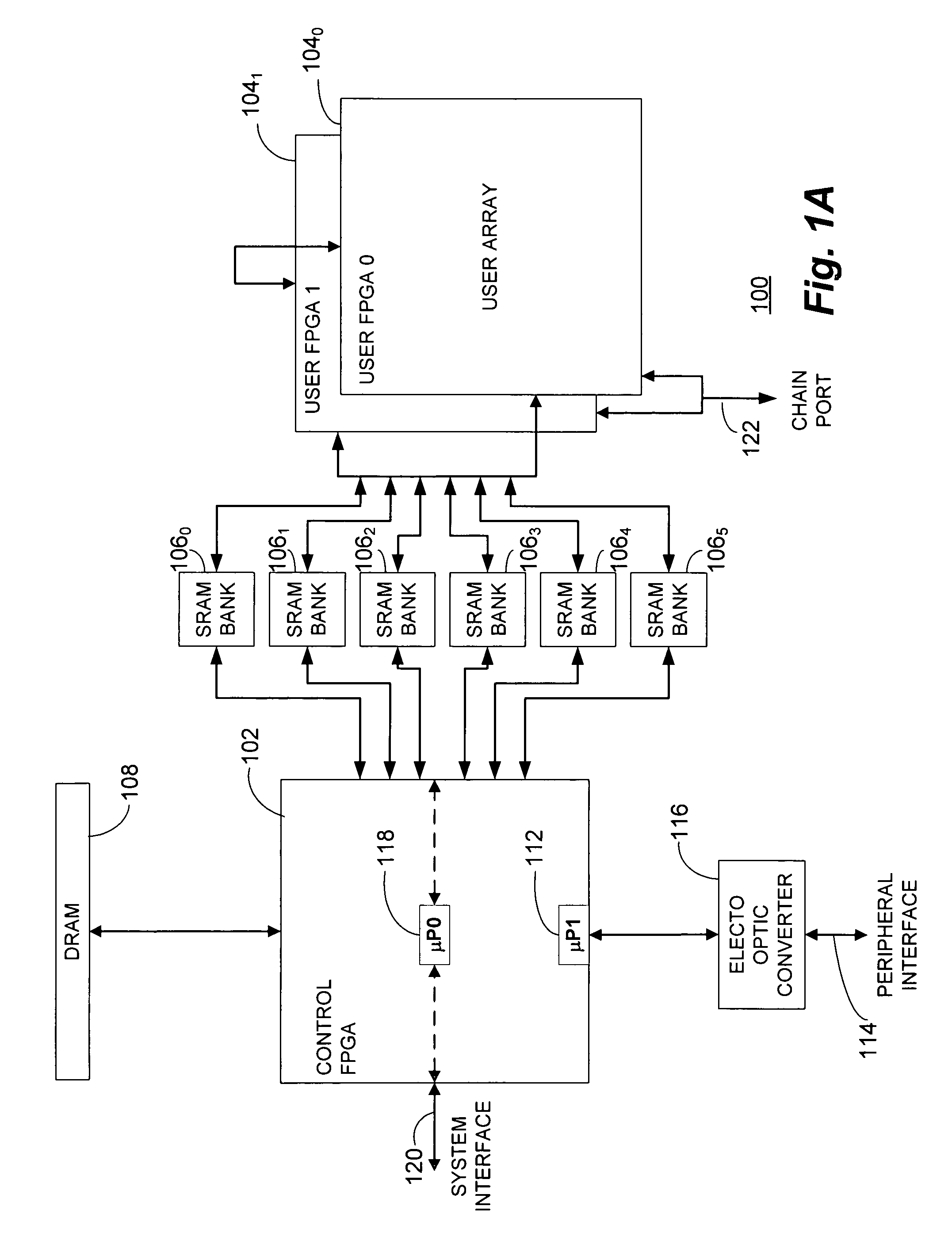
[0037]With reference now to FIG. 1A, a functional block diagram of a particular, representative embodiment of a multi-adaptive processor element 100 is shown. The multi-adaptive processor element 100 comprises, in pertinent part, a discrete control FPGA 102 operating in conjunction with a pair of separate user FPGAs 1040 and 1041. The control FPGA 102 and user FPGAs 1040 and 1041 are coupled through a number of SRAM banks 106, here illustrated in this particular implementation, as dual-ported SRAM banks 1060 through 1065. An additional memory block comprising DRAM 108 is also associated with the control FPGA 102.

[0038]The control FPGA 102 includes a number of embedded microprocessor cores including μP1112 which is coupled to a peripheral interface bus 114 by means of an electro optic converter 116 to provide the capability for additional physical length for the bus 114 to drive any connected peripheral devices (not shown). A second microprocessor core μP0118 is utilized to manage th...


PUM


Abstract

A reconfigurable processor element incorporating both course and fine grained reconfigurable elements. In alternative implementations, the present invention may comprise a reconfigurable processor comprising both reconfigurable devices with fine grained logic elements and reconfigurable devices with course grained logic elements or a reconfigurable processor comprising both reconfigurable devices with fine grained elements and non-reconfigurable devices with course grained elements.

Description

CROSS REFERENCE TO RELATED PATENTS[0001]The present invention is related to the subject matter of U.S. Pat. Nos. 6,076,152; 6,247,110 and 6,339,819 assigned to SRC Computers, Inc., Colorado Springs, Colo., assignee of the present invention. The present application claims priority from, and is a continuation-in-part application of, U.S. patent application Ser. No. 11 / 119,598 filed May 2, 2005 for: “Adaptive Processor Architecture Incorporating a Field Programmable Gate Array Control Element Having At Least One Embedded Microprocessor Core” which is a divisional application of U.S. patent application Ser. No. 10 / 142,045 filed May 9, 2002 now abandoned. The disclosures of the foregoing United States Patents and Patent Applications are specifically incorporated herein by this reference in their entirety.BACKGROUND OF THE INVENTION[0002]The present invention relates, in general, to the field of adaptive or reconfigurable processors. More particularly, the present invention relates to a m...

Claims


Application Information

Patent Timeline
Patent Type & Authority Patents(United States)
IPC IPC(8): G06F9/00
CPCG06F15/7867H05K1/181H05K1/0286H05K2201/10734H05K2201/10212H05K2201/10545Y02P70/50
Inventor HUPPENTHAL, JON M.KELLAM, DENIS O.
Owner SRC COMP
Learn More