
System and method for remote assembly of messages to create a control message

a message and control technology, applied in the field of distributed system components, to achieve the effect of avoiding device and connection constraints

Active Publication Date: 2008-01-08
MITEL
View PDF14 Cites 20 Cited by
  • Summary
  • Abstract
  • Description
  • Claims
  • Application Information

AI Technical Summary

Benefits of technology

[0015]According to the present invention, a method and system are provided for addressing the above-discussed need while overcoming the limitations of the prior art. Generally, the invention provides for assembly of information to create a control message that is implemented outside of the wireless device, thereby avoiding device and connection constraints. The technique of the present invention provides this functionality by allowing a ‘remote assembly’ of messages in a way that allows the originator to retain control over services that are assembled in creating the full service.
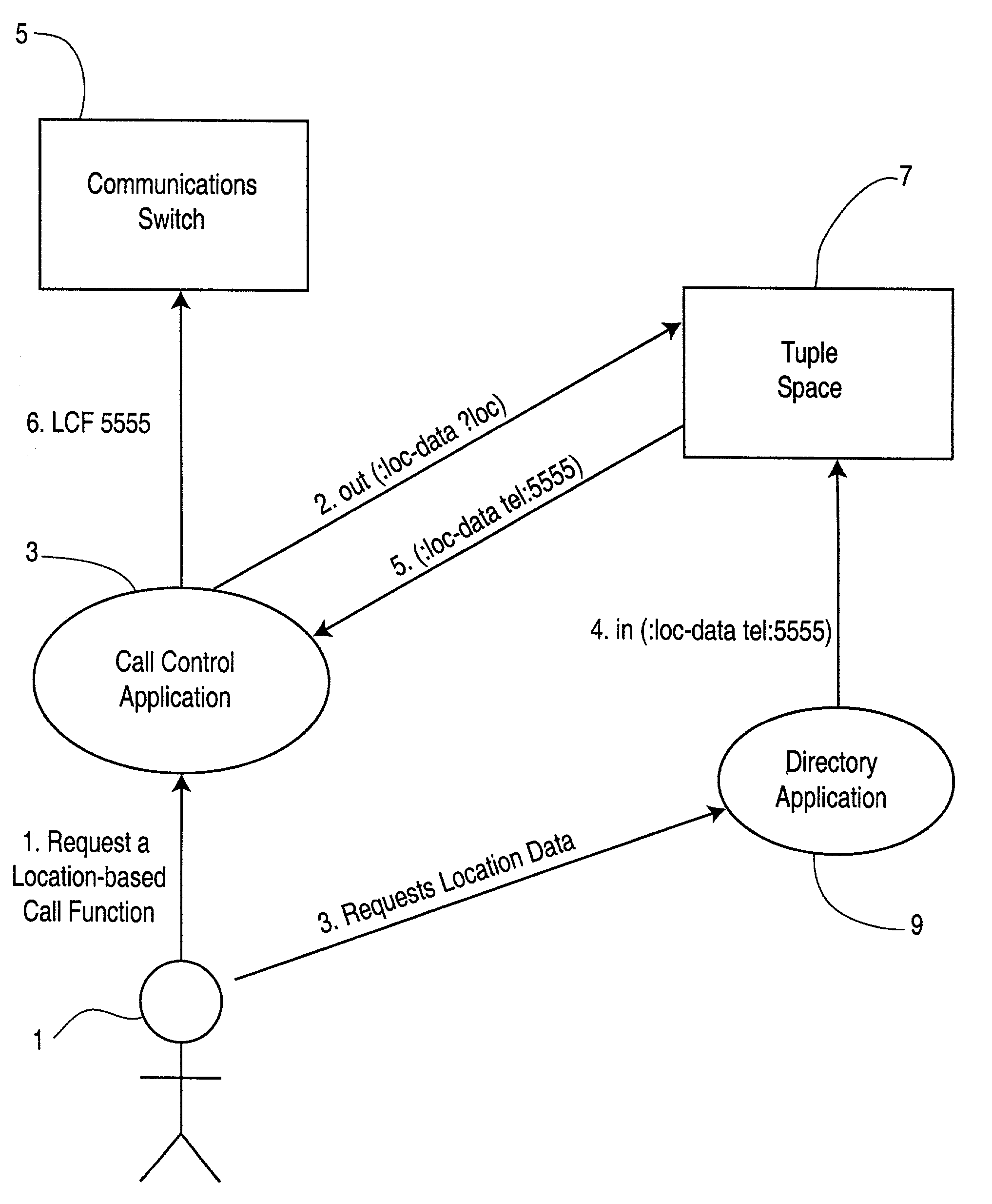
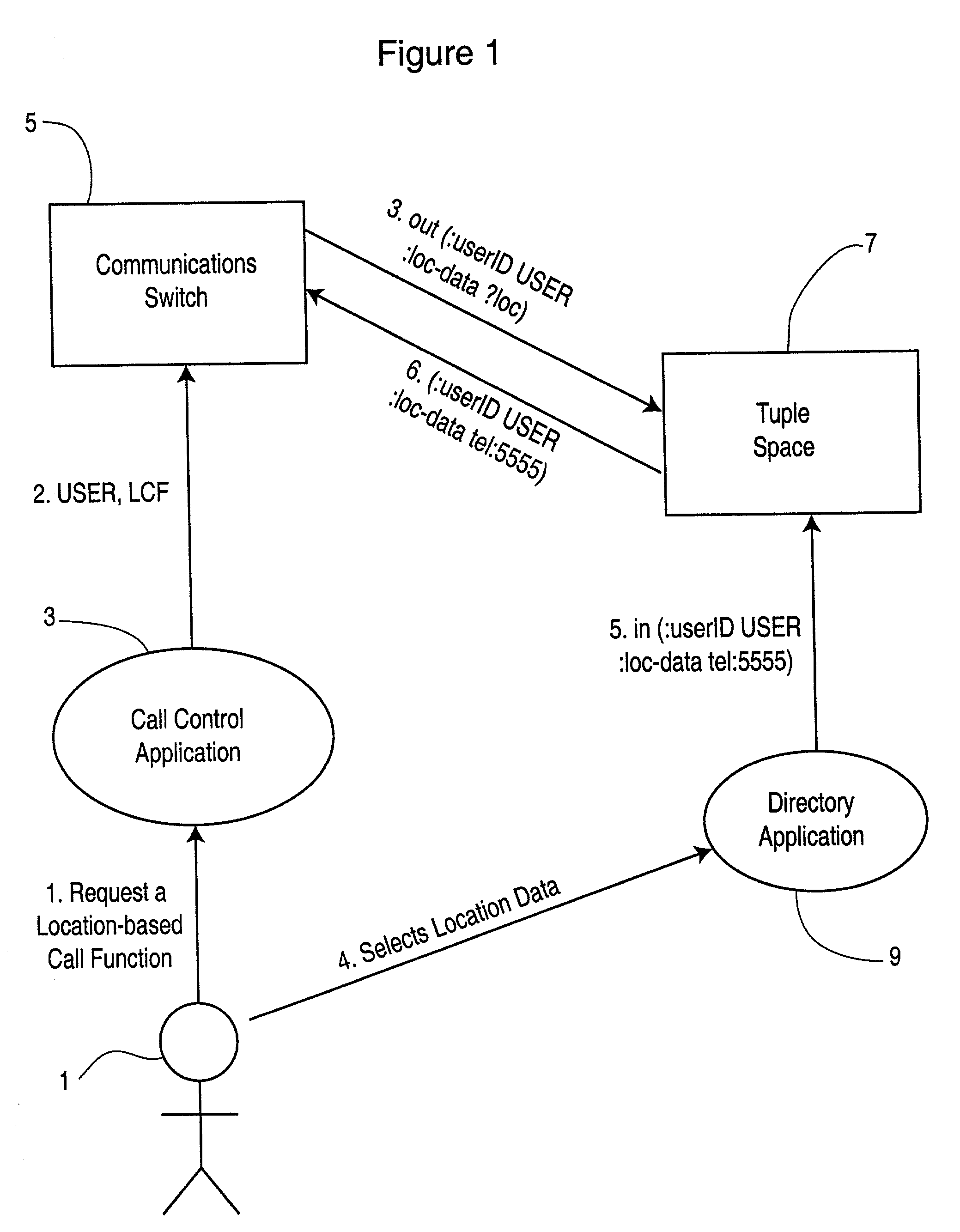
[0017]One example of such an action is the sending of a message indicating that a user wishes to call a specific person who is mobile. This requires that the originator determine where the mobile person is located, by consulting a location service. It is common that the user would also require authorization to contact the mobile person in a specific way (i.e. long distance charges etc.) Thus, the user may be required to contact an authorization service for an authorization token. In a conventional system, the originator assembles a message and forwards it to a service provider. However gathering the necessary information requires several messaging steps using the wireless link. The use of a coordination space as taught by the present invention allows the location and authorization services to place information in the coordination space and for the communication switch that executes the message to obtain the message from the space by a method of implicit assembly. More particularly, the originator sends messages to the communication switch to alert it that the process is about to begin, and to the location and authorization services to require them to post information to the coordination space. The communication switch gathers this information and puts it together with the message information that it receives from the originator to implicitly generate the message.
[0018]The ‘remote assembly’ model according to the present invention enjoys the benefits of both the remote messaging and remote execution models without the disadvantages set forth above. The system of the present invention conserves bandwidth in the same way as the remote execution model but also maintains the security advantages of the remote messaging model. Remote assembly according to the present invention maintains the benefits of loose coupling which are provided by remote messaging and remote execution over the remote method invocation and remote procedure call models.
[0019]As discussed above, in the remote assembly model messages are not required to be created at an isolated component (e.g. accessible only over a low speed wireless link). Instead a group of components cooperate together to assemble a message in the coordination space, thereby obviating the need to create messages in an isolated location and send them over a low speed link.
[0020]This is especially important in applications where a message has to be assembled from information that is available only from directories in the network. Queries are sent to more than one directory and potentially large objects are retrieved from them. These objects are processed and assembled into a message and sent over the low speed link. According to the prior art, many traversals of the low speed link would be required to do retrieve such potentially large objects. The remote assembly method of the present invention is designed to eliminate the need for these wasteful traversals.

Problems solved by technology

However gathering the necessary information requires several messaging steps using the wireless link.

Method used


Image

  • System and method for remote assembly of messages to create a control message
  • System and method for remote assembly of messages to create a control message
  • System and method for remote assembly of messages to create a control message

Examples


Embodiment Construction

[0026]Before describing the ‘remote assembly model’ of the invention in detail, a brief description is provided herein below of several different techniques for the creation of applications among multiple components.

[0027]A very common technique is to represent each component as an object and for each of the components to provide an API of method calls by which other components can control it. A well-known difficulty of this technique relates to intimately tying the implementations of multiple components together. A change in one component's implementation needs to be analyzed in order to discover how the change impacts the implementations of other components. This has obvious implications on system stability and evolution.

[0028]One solution to this problem is a prior art model of message passing in which an agreement is made on a set of standard messages, which can control an application. This decouples implementations since all commonality is now contained within the agreed messag...


PUM


Abstract

A system for remote assembly of messages to create a control message includes a shared coordination space for assembly of messages, and a plurality of components for performing predefined actions and for exchanging messages according to a predetermined ontology. The plurality of components includes a first component for directing other ones of the components to publish information on the coordination space and in response gather several distinct pieces of the information and assemble the distinct pieces as a message by which to control the actions of the component. According to a preferred embodiment, the shared coordination space is a tuple space, one of the components is a call control application for controlling a communication switch, and at least one other component is a directory application containing location information.

Description

RELATED APPLICATIONS[0001]This application claims priority to U.K. Patent Application No. 0110713.5, filed May 2, 2001 (now abandoned), which is hereby incorporated by reference.FIELD OF THE INVENTION[0002]The present invention relates in general to the problem of component coordination in distributed systems, and more particularly to a system for remote assembly of messages for maintaining low latency collaboration among components while conserving bandwidth, particularly in wireless systems.BACKGROUND OF THE INVENTION[0003]Distributed network based systems are now commonly for the provision and creation of useful applications. Components (agent, objects . . . ) are distributed on a network and cooperate together to provide desired services. Several techniques have been proposed to provide for the interaction of these components. These techniques are characterized by unique advantages and disadvantages. This disclosure describes a new system which improves on such prior art techniq...

Claims


Application Information

Patent Timeline
IPC IPC(8): G06F13/00H04M3/42H04M3/493H04W4/02H04W12/02
CPCH04M3/42H04M3/42348H04M3/4931H04W4/02H04M2207/18H04M2242/14H04W12/02H04W4/12
Inventor LISCANO, RAMIROFULLARTON, SONYAMUSSBACHER, GUNTERGRAY, TOM
Owner MITEL
Learn More