Arrangement having at least one long-stator linear motor, for operating magnetically levitated vehicles

a technology of magnetically levitation and linear motors, which is applied in the direction of motor/generator/converter stoppers, multiple dynamo-motor starters, dynamo-electric converter control, etc., and can solve the problems of no longer being changed, not in any way acceptable, and timing of services

Active Publication Date: 2007-02-06
SIEMENS AG
View PDF17 Cites 2 Cited by
  • Summary
  • Abstract
  • Description
  • Claims
  • Application Information

AI Technical Summary

Benefits of technology

[0006]A further object of the invention is to improve the arrangement such that different frequencies of service for the vehicles can be obtained without any major changes to the hardware.
[0007]Yet another object of the invention is to make it possible to bring the vehicles closer together than has been usual hitherto by up to half of the intervals between them.
[0009]These and other objects are solved by an arrangement which is characterized in accordance with the present invention in that, to make different frequencies of service possible for the vehicles or in other words to make different intervals possible between the vehicles, at least one motor region is provided with at least one region boundary which is arranged to be variable.
[0010]In the same way as hitherto, the invention takes it as a basis that, at any point, precisely one motor region will always be assigned to each vehicle travelling on a track. However, in contrast to previous solutions, the boundaries of these motor regions are not permanently assigned to given sections of the track but are variable as a function of the frequencies of service, thus enabling longer motor regions to be made available for faster vehicles and shorter ones for shorter vehicles for example, and hence also enabling the intervals between vehicles travelling at different speeds to be adjusted to suit requirements. In other words, the motor regions along the track can be sub-divided in a different way without changing the number of motor regions. The structural changes required for this purpose call for only comparatively modest expenditure and can be made without any loss in power for the motor. Also, the invention has the advantage that it can be applied both to single-feed linear motors and to double-feed linear motors.

Problems solved by technology

This means that the timing of services or the frequencies of service, i.e. the intervals between the vehicles, and the timetable when vehicles are at the maximum permitted frequency are preset at fixed figures by the lengths of the motor regions and can no longer be changed once a railway for magnetic levitation has been built.
This is not in any way acceptable in view of the considerable increase in the cost of installation that it involves and the fact that the need for non-uniform frequencies of service generally only exists for a certain time, i.e. at given times of day or when there are unforeseen operating conditions.

Method used


Image

  • Arrangement having at least one long-stator linear motor, for operating magnetically levitated vehicles
  • Arrangement having at least one long-stator linear motor, for operating magnetically levitated vehicles
  • Arrangement having at least one long-stator linear motor, for operating magnetically levitated vehicles

Examples


Embodiment Construction

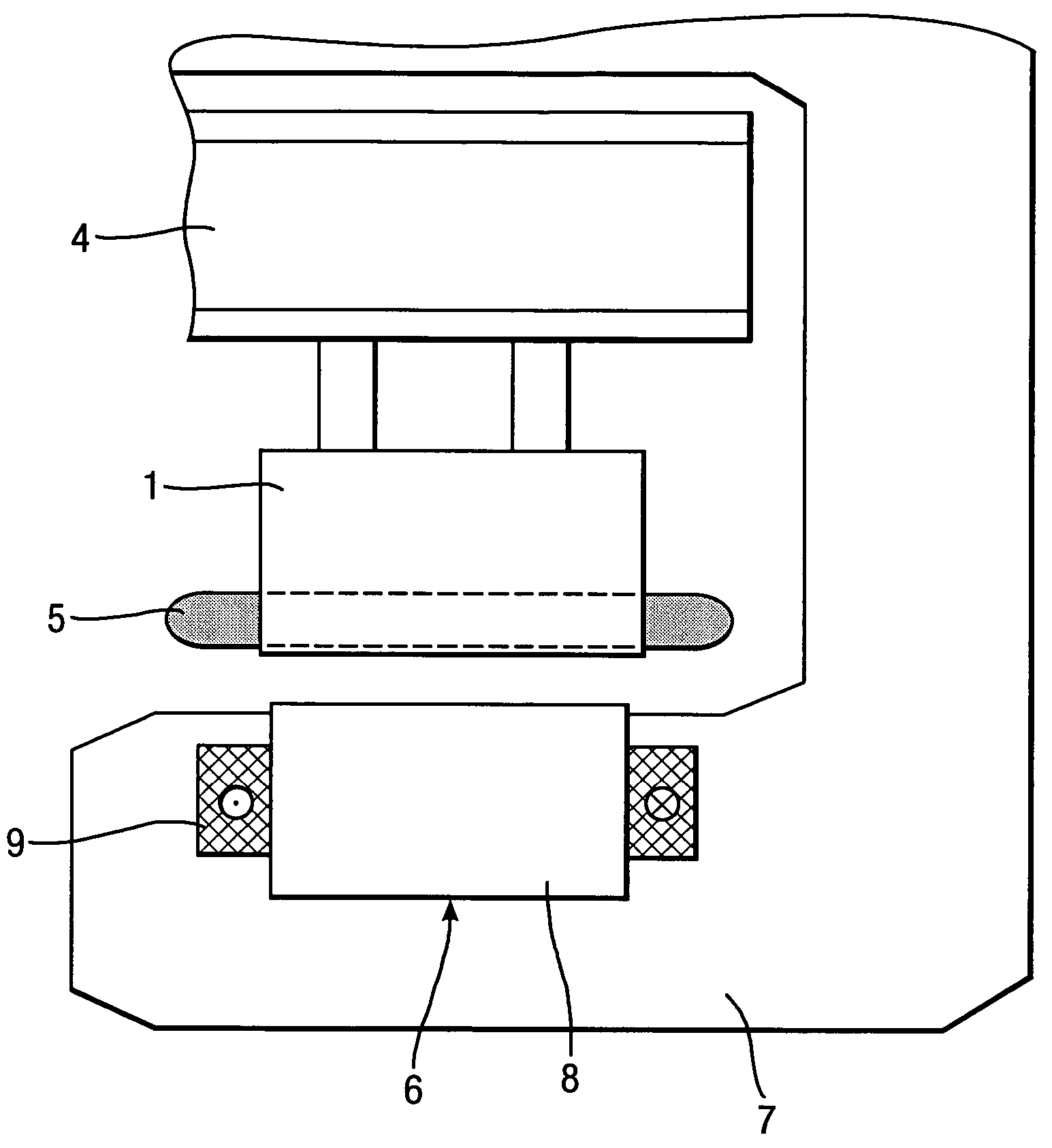
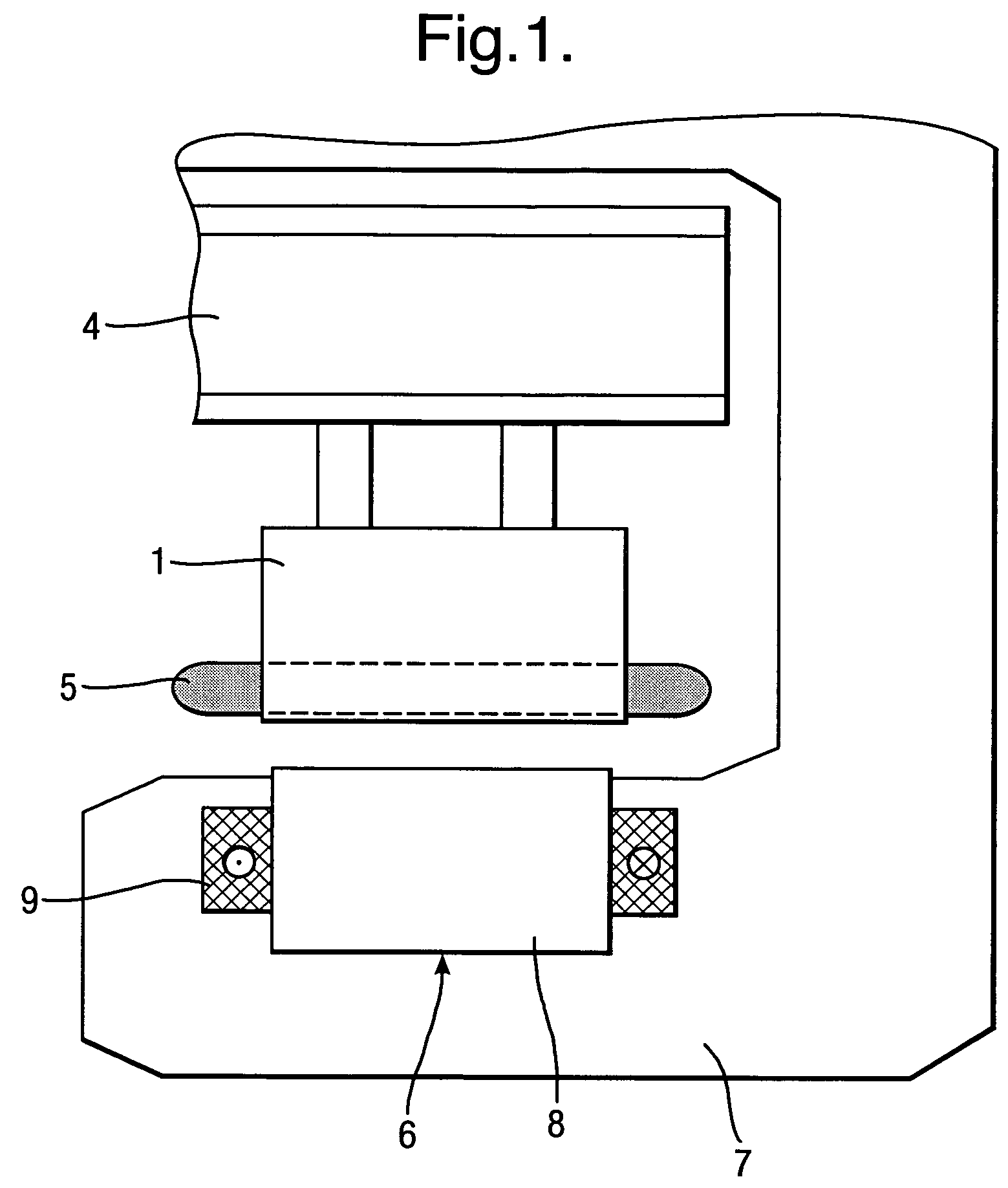
[0018]On a magnetically levitated railway having a synchronous long-stator linear motor (FIGS. 1 and 2), a laminated stator core 1, which has a plurality of slots and teeth arranged in succession to one another, is connected in a fixed position to a track 4 which is set up along a preset route. Inserted in the slots in the laminated stator core 1 is a long-stator winding 5 in the form of a three-phase winding which is fed with three-phase current of variable amplitude and frequency by a converter, as a result of which an advancing or travelling (transient) wave is set up in a known fashion longitudinally of the long-stator linear motor. The exciter field of the long-stator linear motor is generated by an exciter arrangement 6 which is formed by a plurality of magnets which are mounted on a vehicle 7, which are arranged in a distributed fashion in the latter's longitudinal direction, which at the same time perform a supporting function and which each comprise a magnet core 8 and an e...


PUM


Abstract

The invention relates to an arrangement for operating a magnetically levitated vehicle by means of an arrangement having at least one long-stator linear motor. The linear motors are sub-divided, longitudinally of a track, into individual motor regions (A) in each of which only one vehicle (7) is able to travel at a time. To make possible different frequencies of service for the vehicles (7), i.e. different intervals between the vehicles (7), the region boundaries (B) between at least two motor regions (A1, A2) which follow one another in the direction of travel are arranged to be variable.

Description

FIELD OF THE INVENTION[0001]The invention relates to an arrangement for operating magnetically levitated vehicles, comprising: at least one a.c. winding which is laid out longitudinally of a track and is sub-divided into winding sections, an exciter arrangement which is mounted on the vehicle, track-segment cables arranged longitudinally of the track, voltage sources arranged at a distance longitudinally of the track, switching means, control means connected to the latter for connecting the winding sections in succession to assigned track-segment cables and voltage sources in line with the movement of the vehicle, and motor regions which follow one another in the direction of the track which are formed by assigned winding sections, track-segment cables and voltage sources, and which are marked off from one another by region boundaries such that in each of said motor regions only one vehicle can be operated.BACKGROUND OF THE INVENTION[0002]In known methods and arrangements of this ki...

Claims


Application Information

Patent Timeline
Patent Type & Authority Patents(United States)
IPC IPC(8): H02P1/00H02K41/00
CPCB60L13/10B60M3/04B60L2200/26
Inventor FISCHPERER, ROLF
Owner SIEMENS AG
Why Eureka
Try Eureka