System and method for embodying virtual reality

Inactive Publication Date: 2007-02-06
ELECTRONICS & TELECOMM RES INST
View PDF5 Cites 35 Cited by
  • Summary
  • Abstract
  • Description
  • Claims
  • Application Information

AI Technical Summary

Benefits of technology

[0007]It is an object of the present invention to provide a virtual real

Problems solved by technology

Since conventional modeling methods use expensive devices to model virtual reality, it is very expensive, and there are many difficulties to overcome in implementing the same.
However, no cu

Method used


Image

  • System and method for embodying virtual reality
  • System and method for embodying virtual reality
  • System and method for embodying virtual reality

Examples


Embodiment Construction

[0025]In the following detailed description, only the preferred embodiment of the invention has been shown and described, simply by way of illustration of the best mode contemplated by the inventor(s) of carrying out the invention. As will be realized, the invention is capable of modification in various obvious respects, all without departing from the invention. Accordingly, the drawings and description are to be regarded as illustrative in nature, and not restrictive.

[0026]A virtual reality embodying system and method will be described with reference to drawings.

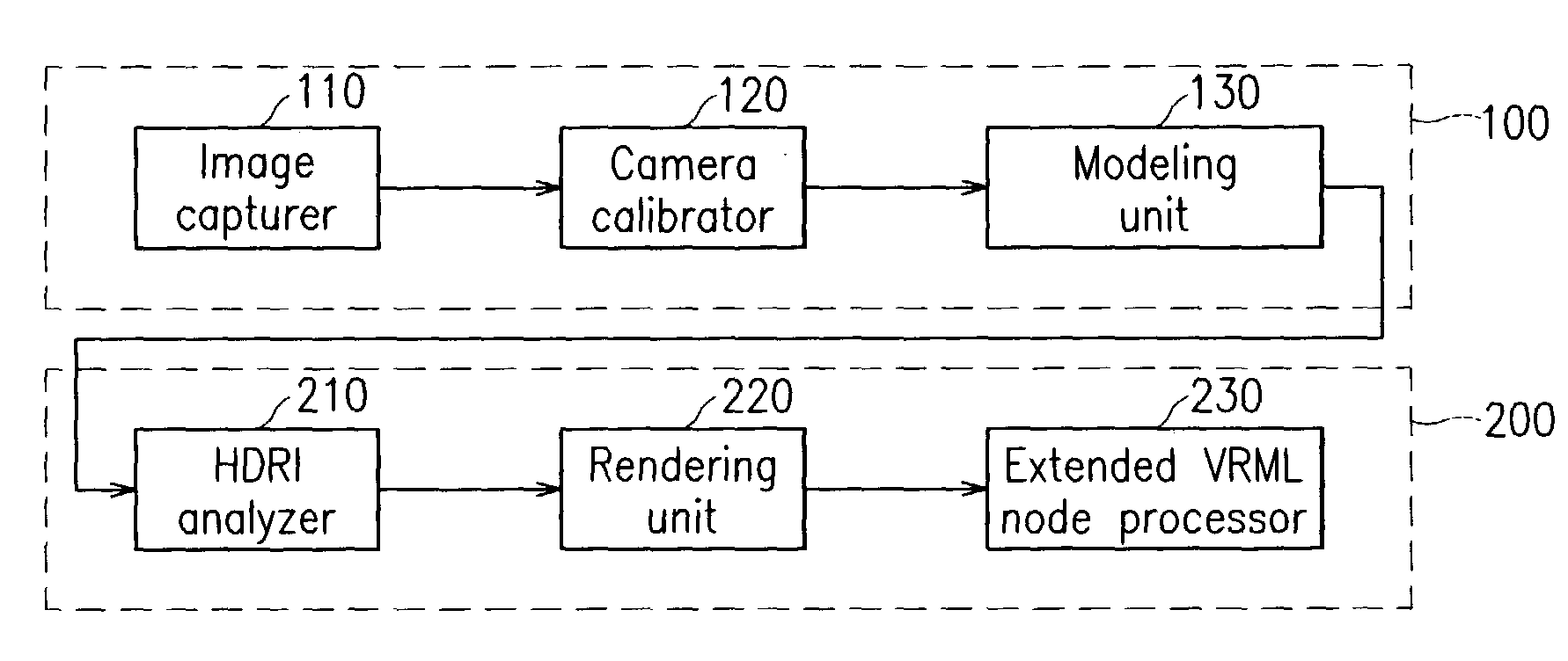
[0027]FIG. 1 shows a rough block diagram for a virtual reality embodying system according to a preferred embodiment of the present invention.

[0028]As shown, the virtual reality embodying system comprises an image-based modeling unit 100, and an image-based rendering unit 200. The image-based modeling unit 100 provides a method for modeling 3D virtual objects including color information by using a plurality of 2D images take...


PUM


Abstract

A virtual reality embodying system uses 2D images and HDRI data taken of a target object through a camera to embody virtual reality. A modeling unit compares the 2D image's coordinate with a real coordinate to calculate a transform matrix, calculates a vanishing point of a reference vector, uses the vanishing point to calculate a camera matrix, uses the camera matrix and the transform matrix to calculate a rotation matrix and a translation matrix, and uses the rotation matrix and the translation matrix to model the 2D image into a virtual model. A rendering unit uses the HDRI data as texture to render the virtual model, and embodies the HDRI into an extended VRML node to apply the virtual model to the VRML environment.

Description

CROSS REFERENCE TO RELATED APPLICATION[0001]This application is based on Korea Patent Application No. 2002-71499 filed on Nov. 18, 2002 in the Korean Intellectual Property Office, the content of which is incorporated herein by reference.BACKGROUND OF THE INVENTION[0002](a) Field of the Invention[0003]The present invention relates to a system and method for embodying virtual reality.[0004](b) Description of the Related Art[0005]Recently, various methods for embodying objects and environments which look identical to the real world into virtual space have been attempted in research fields of modeling and rendering of objects. Since conventional modeling methods use expensive devices to model virtual reality, it is very expensive, and there are many difficulties to overcome in implementing the same.[0006]Therefore, requirements for minimum pieces of the devices and easy access methods tend to increase, and accordingly, methods for embodying 3-dimensional (3D) virtual models using a plur...

Claims


Application Information

Patent Timeline
IPC IPC(8): G06K9/00G06K9/68G06T15/00G06T17/00G06T7/00G06T15/20G09G5/00H04N13/00
CPCG06T7/0018H04N13/0275G06T15/20G06T7/80H04N13/275G06T17/00
Inventor KOO, BON-KIKIM, SUNG-YEKIM, HAE-DONGKIM, JAE-CHULCHOI, BYOUNG-TAE
Owner ELECTRONICS & TELECOMM RES INST
Why Eureka
Try Eureka