General purpose accessory for a cochlear implant system

a cochlear implant and accessory technology, applied in the field of general purpose accessories for cochlear implant systems, can solve the problems of inability to derive suitable benefits from conventional hearing aid systems, large units, and reduced behind-the-ear units, and achieve the effect of more power or power

Inactive Publication Date: 2007-02-06
COCHLEAR LIMITED
View PDF3 Cites 43 Cited by
  • Summary
  • Abstract
  • Description
  • Claims
  • Application Information

AI Technical Summary

Benefits of technology

[0017]As described, it is considered that with the increasing popularity of behind-the-ear units or even take up of in-the-ear units, cochlear implant system recipients will expect such devices to provide features additional to those considered as standard at present. The present invention is directed to meeting this expectation while ensuing that the unit remain at an acceptably small size. The additional features envisaged as being required as standard include: a built in telecoil for picking up signals from a telephone; the ability to detect sounds from both side of the head rather than just the side of the head that the BTE unit is positioned on; sufficient power resources to use all speech processing strategies; adequate battery life to enable the device to operate for a significant time without the need to recharge or replace the batteries; and a radio receiver and the like for classroom or other remote signal source use.
[0022]The use of a power source in the second unit can provide a number of advantages. For example, the power source of the second unit cam provide the implantee with more power or power for a longer time than is available from the use alone of an on-board power source. Saying this, the first unit can, in one embodiment, have an on-board power source.
[0023]The use of the power source in the second unit also potentially allows a reduction in the dimensions of the first unit as a smaller on-board power source can potentially be utilised due to the presence of the additional power source in the second unit.
[0073]In the aspects provided herein, the receiver unit can comprise a telecoil. Telecoils are used by hearing impaired listeners in particular situations which usually involve group situations in organised venues, such as classrooms, meeting halls, conference rooms, music halls, cinemas and the like. Telecoils are designed to pick up magnetic fields generated by wire loops which enclose the area. Telecoils are also used to pick up magnetic signals from a telephone to avoid acoustic interference in noisy situations.
[0110]The inventions described herein provide an alternative means that allows the overall dimensions of the external component of a cochlear implant system to either remain substantially the same or be further reduced compared to presently known external components while offering improved performance and / or additional capabilities. It also provides the possibility of allowing for the operation of the cochlear implant system to be shared between the external components allowing the external components to be smaller in dimension and less visible. The present invention also provides the option of allowing the external components to be customised to the requirements of the implantee, taking into consideration the implantee's needs and preferences.

Problems solved by technology

These people are thus unable to derive suitable benefit from conventional hearing aid systems, no matter how loud the acoustic stimulus is made, because there is damage to or absence of the mechanism for nerve impulses to be generated from sound in the normal manner.
While the dimensions of behind-the-ear units have reduced significantly from those worn on the body, the units are typically still larger than most conventional hearing aids due in the main to the space requirements for the speech processor and batteries within this unit as well as the intrinsic differences between hearing aids and cochlear implant devices.
As the power requirements of implant recipients vary depending upon the coding strategies that are employed and the skin flap thickness of the recipient across which the power needs to be transmitted, a main design limitation of conventional behind-the-ear devices has resided in housing a sufficient power supply to cater for all recipient types.
ID order to meet this implantee expectation, it is anticipated that there would need to be an unacceptably large increase in the size of presently known behind the ear units so negating any efforts to further miniaturise such units in the future.

Method used


Image

  • General purpose accessory for a cochlear implant system
  • General purpose accessory for a cochlear implant system
  • General purpose accessory for a cochlear implant system

Examples


Embodiment Construction

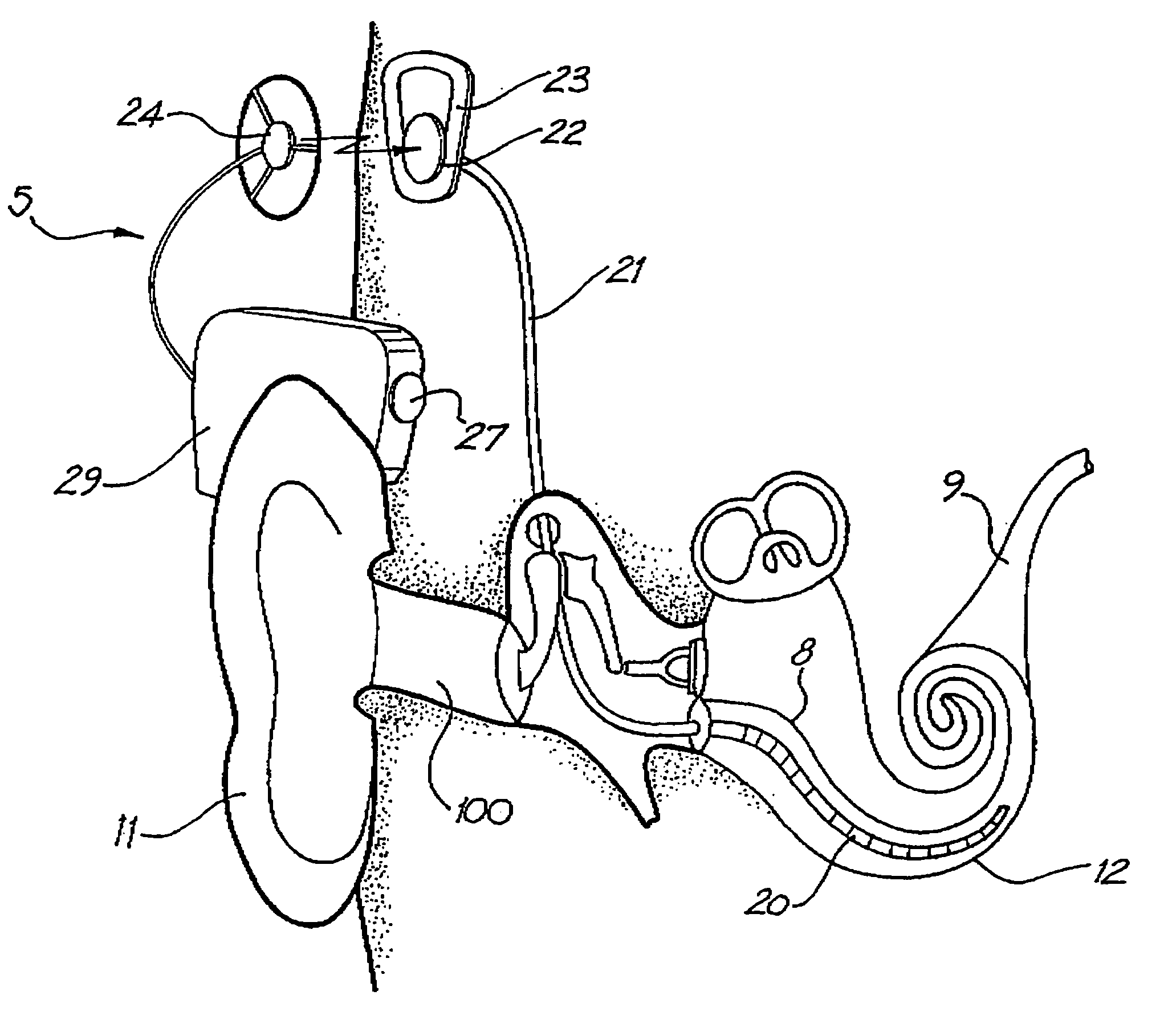
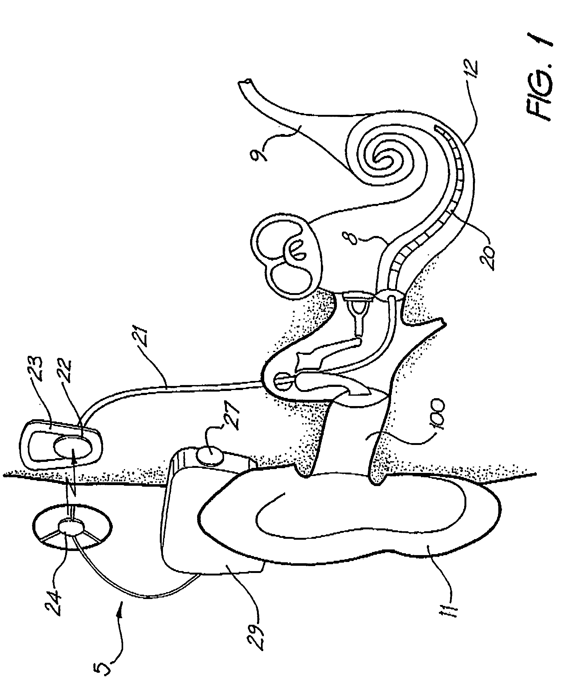
[0120]Before describing the features of the present invention, it is appropriate to briefly describe the construction of one type of known cochlear implant system with reference to FIG. 1.

[0121]One type of known cochlea implant system 5 typically consists of two main components, an external component including a speech processor 29, and an internal component including an implanted receiver and stimulator unit 22. The external component includes an on-board microphone 27. The speech processor 29 is, in this illustration, constructed and an ed so that it can fit behind the outer ear 11. Alternative versions may be worn on the body or within the ear canal 100. Attached to the speech processor 29 is a transmitter coil 24 which transmits electrical signals to the implanted unit 22 via a radio frequency (RF) link.

[0122]The implanted component includes a receiver coil 23 for receiving power and data from the transmitter coil 24. A cable 21 extends from the implanted receiver and stimulator...


PUM


Abstract

A cochlear implant system comprising a first unit (5) adapted to be worn on or in one ear of an implantee. The first unit has a case housing componentry including a microphone (27), and a speech processor means (29). A second unit or accessory (30) is adapted to be worn on or in the other ear of the implantee. The second unit or accessory (30) has a case (31) housing a second power source. An electrical conduction means (58) for transmitting power from the second power source to the componentry of the first unit extends between the first and second units. Such a conduction means (58) can extend around the back of the head of the implantee.

Description

CROSS-REFERENCE TO RELATED APPLICATION[0001]This application is a National Phase Patent Application of International Application Number PCT / AU02 / 00036, filed on Jan. 14, 2002, which claims priority of Australian Patent Application Number PR 2504, filed Jan. 12, 2001.FIELD OF THE INVENTION[0002]The present invention relates to an accessory for use with a cochlear implant system.BACKGROUND OF THE INVENTION[0003]In many people who are profoundly deaf, the reason for deafness is absence of, or destruction of, the hair cells in the cochlea which transduce acoustic data signals into nerve impulses. These people are thus unable to derive suitable benefit from conventional hearing aid systems, no matter how loud the acoustic stimulus is made, because there is damage to or absence of the mechanism for nerve impulses to be generated from sound in the normal manner.[0004]It is for this purpose that cochlear implant systems have been developed. Such systems bypass the hair cells in the cochlea ...

Claims


Application Information

Patent Timeline
Patent Type & Authority Patents(United States)
IPC IPC(8): A61N1/00A61N1/36H04R25/00
CPCA61N1/36032H04R25/558H04R25/556A61N1/36038H04R25/607
Inventor SELIGMAN, PETER
Owner COCHLEAR LIMITED
Why Eureka
Try Eureka